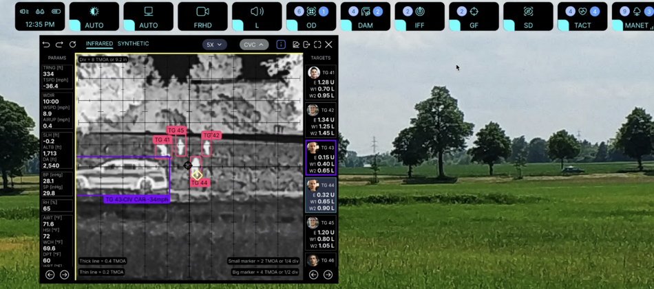
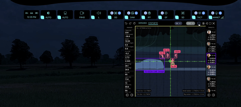
Public:Applications: Difference between revisions
| Line 1,685: | Line 1,685: | ||
'''Interface examples''' | '''Interface examples''' | ||
[[File:UI-example-12.png|frameless|950x950px]] | |||
[[File:UI-example-21.png|frameless|950x950px]] | |||
'''{{#info-tooltip: More info}} ''<u>Insert picture for example</u>''<br><br>''' | '''{{#info-tooltip: More info}} ''<u>Insert picture for example</u>''<br><br>''' | ||
Revision as of 13:17, 20 August 2024
Abstract
![]() →redirect Further information: Public:ARHUDFM Manifesto, Public:Graphical User Interface, Public:ARHUDFM Features Summary, Public:DoD_Pains
→redirect Further information: Public:ARHUDFM Manifesto, Public:Graphical User Interface, Public:ARHUDFM Features Summary, Public:DoD_Pains
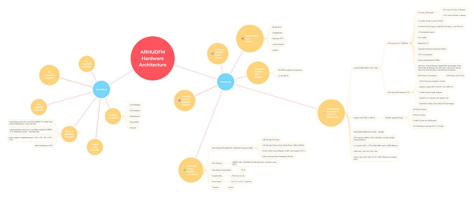
Augmented Reality Heald-Up Display Fullface Mask (ARHUDFM) is a complex device that is not easy to understand at a first look, because there are little relevant examples to compare. Therefore, we suggest that you first read the information on the Public:ARHUDFM Manifesto page.
This page describes the structure and contents of the applications used in the ARHUDFM device.
App names in alphabetic order
![]() →redirect Further information: Public:Graphical User Interface, Public:Voice User Interface
→redirect Further information: Public:Graphical User Interface, Public:Voice User Interface
The applications are listed here in alphabetical order of their abbreviated names. Links are active.
| A | B | C | D | E | F | G | H | I | J | K | L | M |
|---|---|---|---|---|---|---|---|---|---|---|---|---|
| ACC | BSVE | CAC | DISP | EODD | FA | 4/5G | HF | IFF | ||||
| ADM | BT | CAL | DRON | FILE | GFL | HT | IMSG | MAP | ||||
| ANLS | CAM | DVC | FPAD | GNSS | INP | MMD | ||||||
| ANTC | CHAT | FTRC | MMC | |||||||||
| APAR | CRPT | MSG | ||||||||||
| CVC |
| N | O | P | Q | R | S | T | U | V | W | X | Y | Z |
|---|---|---|---|---|---|---|---|---|---|---|---|---|
| NAV | P2P | RADR | SDA | TESS | UHF | VBS | WGR | |||||
| NET | PATH | RBRC | SDR2 | TIPS | UVRC | VHF | WIKI | |||||
| NOTS | PCSR | RC | SDRS | TIME | VM | WLAN | ||||||
| PLAN | RDF | SEC | TRSL | VOVR | WSVE | |||||||
| PLAY | REC | SENS | TSK | |||||||||
| PROC | RFDD | SGHT | ||||||||||
| PTTH | RPAC | SINT | ||||||||||
| RWRC | SPOT | |||||||||||
| SRV | ||||||||||||
| STM | ||||||||||||
| STT | ||||||||||||
| SYS |
Application groups
Here are the groups of applications. Links are active.
![]() →redirect Further information: Public:Graphical User Interface, Public:Voice User Interface
→redirect Further information: Public:Graphical User Interface, Public:Voice User Interface
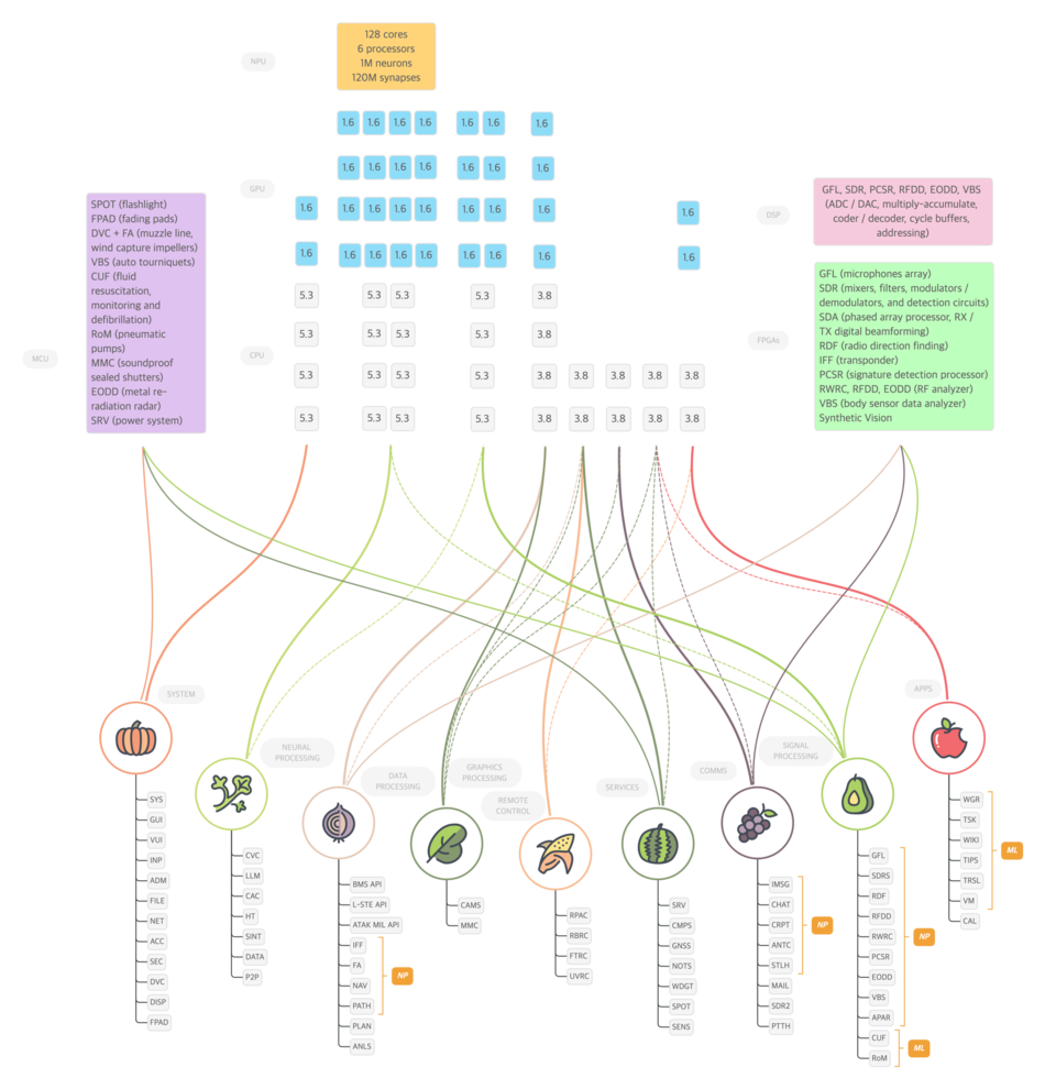
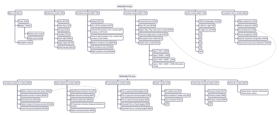
This shows where the above applications are located in the status menu structure with a path to the app.
Status Bar
Main Menu
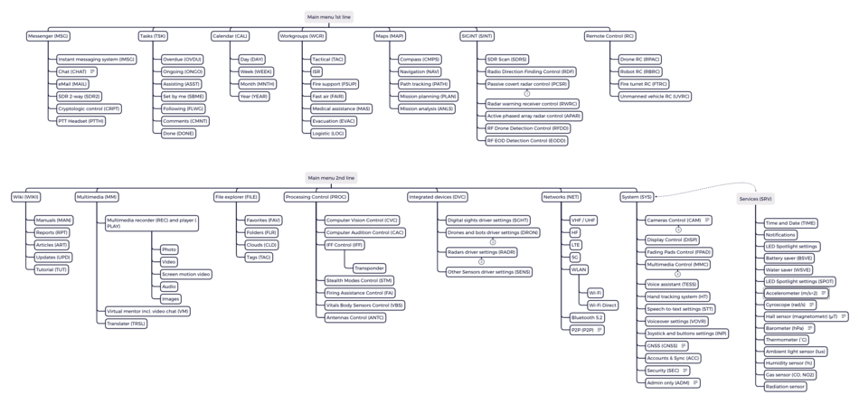
This shows where the above applications are located in the main menu structure with a short note.
For a brief description of the application's functions, see "SB Presets" and " Left main menu (LMM) and Right submenu (RSB )". A more meaningful explanation is found at the bottom of the table in the following sections. You will find a detailed description of the functionality of the applications on the pages of the same name for each application, see the links in the sections below and at the bottom of each page of the project.
| Indication | Left Main menu item name | Indication | Right Submenu Apps or Filters item name | Notice |
|---|---|---|---|---|
| MSG | Messenger | IMSG | Instant messaging system | Large characters appear on the screen and are read by other users instantly. Messages are generated automatically based on the sender's voice commands and gestures. Special operations forces are familiar with this system. We have improved it. |
| CHAT | Chat | Uses Speech-to-text, Voiceover services, TESS voice assistant, so text input and reading is possible but not required | ||
| eMail client | ||||
| SDR2 | SDR 2-way | This is a built-in software-defined radio for communications, which allows you to use much more features (frequencies, modulations, encryption) than the radios used | ||
| CRPT | Cryptologic control | |||
| PTTH | PTT Headset | A software headset that allows you to use a portable handheld radio without using your hands or with buttons on the ear cup of the left headphone earpiece | ||
| TSK | Tasks | OVRD | Overdue | |
| ONGO | Ongoing | |||
| ASST | Assisting | |||
| SBME | Set by me | |||
| FLLW | Following | |||
| CMNT | Comments | |||
| DONE | Done | |||
| CAL | Calendar | DAY | Day | |
| WEEK | Week | |||
| MNTH | Month | |||
| YEAR | Year | |||
| WGR | Workgroups | TACT | Tactical | |
| ISR | ISR | |||
| FIRE | Fire support | |||
| FAIR | Fast air | |||
| MED | Medical assist | |||
| EVAC | Evacuation | |||
| LOG | Logistic | |||
| MAP | Map and Navigation | NAV | Navigation | |
| PATH | Path tracking | |||
| PLAN | Mission planning | |||
| ANLS | Mission analyzing | |||
| SINT | Signal Intelligence | SDRS | SDR Scan | 2 kHz - 6 GHz, essential component for IFF, RPAC apps |
| RDF | Radio direction finding control | Generic SIGINT element and geospatial positioning | ||
| PCSR | Passive covert radar control | Active electronically scanned array (AESA) receive module only | ||
| RWRC | Radar warning receiver control | |||
| APAR | Active phased array radar control | |||
| RFDD | RF Drone detection control | |||
| EODD | RF EOD detection control | |||
| RC | Remote Control | RPAC | Drone RC | |
| RBRC | Robot RC | |||
| FTRC | Fire turret RC | |||
| UVRC | Unmanned vehicle RC | |||
| WIKI | Wiki | MAN | Manuals | |
| RPT | Reports | |||
| ART | Articles | |||
| UPD | Updates | |||
| TUT | Tutorial | |||
| MMD | Multimedia | REC | Multimedia recorder | Photo, video, screen motion, screenshot |
| PLAY | Multimedia player | Photo, video, screen motion, screenshot, images | ||
| VM | Virtual mentor | incl. video chat | ||
| TRSL | Translater | Translation in both directions | ||
| FILE | File explorer | FAV | Favourites | |
| FLR | Folders | |||
| CLD | Clouds | |||
| TAG | Tags | |||
| PROC | Processing control | CVC | Computer Vision control | |
| CAC | Computer Audiion control | |||
| IFF | IFF control | incl. transponder settings | ||
| STM | Stealth modes control | |||
| FA | Firing Assistance control | |||
| VBS | Vitals Body sensors control | |||
| ANTC | Antennas control | |||
| DVC | Integrated devices | SGHT | Digital sights driver settings | |
| DRON | Drones and bots driver settings | RPA / UAV, Fire turret, Dog bots | ||
| RADR | Radars driver settings | Anti-UAV radar, AESA transmit-receive module - TRM (remote control) small tactical radar, Metal re-radiation radar (transmit-receive module) | ||
| SENS | Other Sensors driver settings | |||
| NET | Networks | VHF | VHF | |
| UHF | UHF | |||
| HF | HF | |||
| 4/5G | LTE and 5G | |||
| WLAN | WLAN | Wi-Fi, Wi-Fi Direct | ||
| BT | Bluetooth 5.2 | |||
| P2P | P2P | Multichannel P2P network, user view exchange, multi-party computing | ||
| SYS | System | CAM | Cameras control | Zoom, filters, modes, mixed, calibration, stereo and external cam modes |
| DISP | Display control | |||
| FPAD | Fading Pads control | |||
| MMC | Multimedia control | Headphones, microphones, handheld radio, loudspeaker | ||
| TESS | Voice assistant | |||
| HT | Hand tracking system | |||
| STT | Speech-to-text settings | |||
| VOVR | Voiceover settings | |||
| INP | Joystick and buttons settings | |||
| GNSS | GNSS | GPS, Galileo, QZSS | ||
| ACC | Accounts & Sync | |||
| SEC | Security | Password and security, emergency alert, SOS settings | ||
| ADM | Admin only | OS, roles, remote administration, clearance, data protect, logs, system performance, etc. | ||
| SRV | Services | Time and Date, Notifications, User tips, LED Spotlight settings, Battery saver, Water saver, Accelerometer, Gyroscope, Hall sensor, Barometer, Thermometer, Ambient light sensor, Humidity sensor, Gas sensor (CO, NO2), Radiation sensor |
Brief of augmented visual perception apps functionality
Here we briefly describe the functionality of the apps. You will find a more detailed description of the applications on their main articles pages. See the links below.
CAM (Cameras control)
![]() →redirect Main Article: Cameras Control, Night Vision, Computer Vision Control
→redirect Main Article: Cameras Control, Night Vision, Computer Vision Control
Features
Goal 1. See beyond human vision
- digital zoom up to 24x with interpolation
- HD, HDR (high dynamic range), SWIR (short-wave infrared), LWIR (long-wave infrared) range of light waves day and night in any weather
- dynamic transformation (software filters to improve visibility)
- mixed vision (edge enhancement, contrast color enhancement)
- rear view camera
- sight camera allows you to have a viewpoint from behind cover
- drone or robot camera allows you to see from another viewpoint (aerial view, robot view, another user view)
Goal 2. Use visual content
- stereoscopic vision allows using triangulation to measure the distance, size of objects and speed (when moving towards, approach speed and angular speed along the horizon) without emitting a laser beam (the laser beam unmasks the user)
- built-in cameras capture images of the hands for the gesture control system (Hand tracking)
- built-in and external cameras capture images for the Computer Vision system (detection, recognition)
- the image can be recorded with different quality, bit rate[1] (compression ratio), frame rate, to share with others or use later
The application starts in startup mode.
Advantages
- digital cameras and optics for them are more compact and have less mass, less risk of damage than conventional optics
- digital cameras are multifunctional and cheaper than conventional optics (more features for the same money)
- SWIR mode, in addition to night vision, is suitable for daytime use: vision through fog, observation of the sky, objects on the water surface, visibility of people in camouflage and camouflaged objects, booby traps, plastic and metal mines, technical inspection of equipment and objects
- LWIR mode, in addition to night vision, is suitable for daytime observation of the battlefield (hot barrels, footprints, massive metal camouflaged objects, people in camouflage, especially exposed skin, at ambient temperatures below 85°F, especially when solar activity is favorable, which forms temperature contrasts
Hardware
- Image capture with a three-sensor front stereo camera. One lens transmits the image to the separating prisms and then to 3 sensors.
- (a) DSLR 64 MP Hawk-eye, diagonal 9.25 mm (7.4 x 5.55 mm), type 1/1.7" (9,152 x 6,944 px, 1.32:1, x16 zoom, manual / autofocus) IR-cut filter removable, view angle 84° or 12K sensor 80MP (12,288 x 9,310, 1.32:1, x24 zoom, adaptive adjacent pixel interpolation algorithms based on pixel-by-pixel analysis - sharp edges, smooth structure, fine details)[2]
- (b) SenSWIR SONY IMX992, 400-1700 nm, InGaAs (indium gallium arsenide) layer for photoelectric conversion , approx. 5.32 megapixels, type 1/1.4 (11.4 mm diagonal), 3.45 μm, 2134 ppi, QSXGA (2560 x 2048 pixels), 130 fps (ADC 8-bit), 120 fps (ADC 10-bit), 70 fps (ADC 12-bit), Sensitivity TBD
[3][4][5][6][7], also used as the only rear camera sensor
- Camera in LWIR range (thermal image vision)
- Rear view camera in extended visible light range and SWIR
- If necessary, additional sensors are installed using NVG mount
Interface examples
Insert picture for example
CVC (Computer Vision Control)
![]() →redirect Main Article: Computer Vision Control, Night Vision
→redirect Main Article: Computer Vision Control, Night Vision
Features
The dataset of known graphic patterns developed with Deep Learning (AI) is updated from the cloud on the client to the local SSD during the update. During operation, the built-in detection and recognition system based on Machine Learning (AI) technologies (possibly at a speed of 4-12 frames per second) analyzes images in order to identify known patterns. This requires significantly less computing power and time.[8] At the same time, each client (device) saves samples of the results each time and sends them to the server to replenish the dataset and improve the algorithms. CPU and GPU devices are configured in such a way that part of the processing power is reserved only for individual tasks that are processed in parallel threads.
Despite the fact that high image quality is not required for high accuracy of Computer Vision, and some algorithms even take into account adjacent areas between pixels during digital zooming and interpolation taking into account neighboring pixels, we going to create the capability during detection and recognition to use more information than required. Therefore, the same object on the client device will have information from 3 sensors in different light ranges and several frames sequences from each sensor. In total, up to 20-30 images containing information about one object at one time can be analyzed among themselves, and then the resulting patterns will be analyzed again based on the dataset.
In some cases, we provide for the most complex cases of face recognition in a large stream to use the shared (distributed) computing resources of the P2P (peer-to-peer) network. In this combination, data processing will be performed in parallel threads on different devices, and the results will be available to everyone equally or depending on the settings.
One of the advantages of this ARHUDFM technology is the ability to use other data for clarification. So, for example, the same object from a different viewpoint could be detected by another user of the device or using an external camera (drone, robot, sight) and this information, taking into account the distance, the angle of light on the object and the viewpoint, may contain more data. Data exchange within the P2P network allows you to combine the efforts of several devices for identification. Another capability is to use Computer Audition technology in parallel for identification by sound patterns. And the third capability is to use radio wave detection for inanimate objects (SDRS, RDF, passive radar, metal re-radiation radar). The synergy of multiple detection technologies running in parallel threads and integrated with each other offers exciting potential opportunities
The application starts when one of the presets is enabled. Does not start by default.
Presets:
- OD (Object detection) based on a trained neural network (AI) allows you to detect people, equipment, drones, artificial structures from different angles and at different distances, highlighting them on the screen, measuring range, azimuth, elevation, height above the ground, speed, course direction and geopositions, as well as displaying them on the navigation reticle
- Object Detection will be able to detect anti-tank and anti-personnel mines (including plastic mines), trip wires, pendants, IEDs on the ground and drones above with high accuracy
- MD (Motion detection) helps to detect moving objects, people and equipment, ignoring the flights of birds and insects, the movement of clouds. MD mode is recommended to be used in conjunction with Radio Frequency Drone Detection (RFDD) and Computer Audition Detect noises of aircraft motor (DAM) mode
- FD (Facial detection) incl. using LWIR camera sensor and trained neural network helps to detect people's faces
- FR (Facial recognition) using a neural network in communication with the server allows to recognize people's faces for identification (part of the dataset can be stored on a local drive)
- OCR (Optical character recognition) allows to recognize text and other graphic characters for subsequent translation and documentation
- HSTD (Heat and smoke trace detection) helps detect aircraft and missile paths, artillery and mortar fire from closed positions
Interface examples
Insert picture for example
DISP (Display control)
![]() →redirect Main Article: Display Control
→redirect Main Article: Display Control
Features
The application starts in startup mode.
The application controls the modes:
- Windows modes
- Brightness modes
Interface examples
Insert picture for example
FPAD (Fading Pads control)
![]() →redirect Main Article: Fading Pads Control
→redirect Main Article: Fading Pads Control
Features
The application starts in startup mode. The application controls the degree of transparency of the fading pads. The interface contains 58 fading pads, which, depending on the ambient light or the mode selected by the user, instantly change their transparency from 0% (opaque black) to 100% (fully transparent). This is necessary to comply with the interface principles.
When the contrast is sufficient to display most applications in windows, the transparency should remain, because this enables the user to be more aware of the environment. It has the ability to better respond to movement in its field of vision.
Fading windows with varying level of shading can act as screens against dazzling sunlight. The surface of the outer visor is magnetron-coated, creating a filter against UV sunlight, so such screens allow the user not to use sunglasses inside the mask. Users can use optical eyeglasses without restrictions, for this the geometry features are taken into account in the design. The problem of glasses and visor fogging, as it is solved in the device, is described in the Features Summary.
As a rule, windows can be in several appearances, depending on the need for maximization:
- 1:1 - window in its standard minimum size
- 1:2 - window combines two horizontally adjacent
- 2:1 - window combines two vertically adjacent
- a large window combines four windows on the left or right
Interface examples
Insert picture for example
HT (Hand tracking system)
![]() →redirect Main Article: Hand Tracking
→redirect Main Article: Hand Tracking
Features
The application starts in startup mode. The application allows to control the interface using gestures.
- The stereo camera captures the image of the hands and recognizes the user's gestures
- Gesture library constantly updated, Machine Learning allows the user to create custom gestures
- Gestures can indicate not only the state, but also the dynamics, for example, smoothly change the volume level, brightness, etc.
- Capturing and recognizing fingers allows to use software interface controls, including scrollbars, buttons (and a virtual keyboard if necessary), swipe sideways and up and down, scale and rotate screens inside a window, hide and move windows
Interface examples
Insert picture for example
Brief of mixed audial perception apps functionality
Here we briefly describe the functionality of the apps. You will find a more detailed description of the applications on their main articles pages. See the links below.
MMC (Multimedia control)
![]() →redirect Main Article: Multimedia Control
→redirect Main Article: Multimedia Control
Features
The application starts in startup mode. The application allows to configure presets and work with different applications for multimedia devices: headphones, embedded microphones, handheld radio through the built-in hardware headset and voice software headset, loudspeaker.
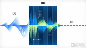
2 insulating layers, airway obturator and seal around face, make the user's voice almost inaudible from the outside. On the other hand, Active noise reduction is applied to dampen unnecessary sound pressure. We assume that the level of counteraction (noise reduction) using this technology will be able to reach ∆80 dB SPL to 15-85 dB SPL (upper limit of normal). However, this unit is an Audial Augmentation type, so the openings in the bottom of the headphones ear cups are permanently open for the perception of the surrounding sound environment with minimal attenuation (less than 10 dB SPL). When the threshold values of the ambient sound pressure are exceeded, these openings are closed with soundproof sealed shutters. The response time of the electromagnetic pushers of the soundproof damper drives is less than 3 ms (0.003 s).
Hardware
- Built-in MEMS (Micro-Electro-Mechanical-Systems) microphone (1) in mask obturator airway to transmit the user's voice
- If the lower part of the mask is not used, a boom microphone (2) with a windproof pad on the flexible goosneck is connected
- 19 cardioid MEMS (dome) microphones allow to perceive sound waves in a wide range of frequencies, including those inaudible to humans, from very low to very high, used in Computer Audition modes, incl. Active noise reduction
- The super-cardioiod and ultra-cardioid microphones with a narrow directivity pattern on the front of the mask allow to accurately determine the source of the sound wave
- Loudspeaker with amplification power up to ∆50 dB SPL allows the user not to shout, but the surrounding people will hear his voice at a distance of several tens of meters, even in conditions of high ambient noise
- Full-size headphones are equipped with large ear cups and ear cushions made of hypoallergenic elastic polyurethane, which are pressed against the head ("circum-aural" - “around the ear”).
- With prolonged use of any headphones, especially indoors and in the heat, the ears usually sweat. In this design, the openings in the bottom of the headphones ear cups are permanently open and provide ventilation
- In places where ear cushions adjoin the scalp, it is recommended to apply a dry antiperspirant cream on the surface of the ear cushions.
Interface examples
Insert picture for example
TESS (Voice assistant)
![]() →redirect Main Article: Voice Assistant
→redirect Main Article: Voice Assistant
Features
The application starts in startup mode. The application is a small language model with the ability to learn on the dataset of a particular user and many users of this platform. Applies AI methods.
Voice commands can be pronounced differently with different accents, so definitive voice commands are not effective (nobody will memorize dozens of voice commands). Instead, a voice assistant is used.
Interface examples
Insert picture for example
STT (Speech-to-text)
![]() →redirect Main Article: Speech-to-text
→redirect Main Article: Speech-to-text
Features
The application starts in startup mode. The application converts the user's voice into text. Applies AI methods.
Voice communication converted to text takes up much less space during transmission, has no distortion, and allows to increase the complexity of encryption when transmitting messages.
Interface examples
Insert picture for example
VOVR (Voiceover)
![]() →redirect Main Article: Voiceover
→redirect Main Article: Voiceover
Features
The application starts in startup mode. The application converts text to voice (speech synthesis). Thus, for example, incoming messages in CHAT can be listened to rather than read.
Interface examples
Insert picture for example
CAC (Computer Audition control)
![]() →redirect Main Article: Computer Audition Control
→redirect Main Article: Computer Audition Control
Features
The dataset of known sound patterns developed with Deep Learning (AI) is updated from the cloud on the client to the local SSD during the update. During operation, the built-in detection and recognition system based on Machine Learning (AI) technologies analyzes sound patterns in order to identify known patterns. This requires significantly less computing power and time. At the same time, each client (device) saves samples of the results each time and sends them to the server to replenish the dataset and improve the algorithms. CPU and GPU devices are configured in such a way that part of the processing power is reserved only for individual tasks that are processed in parallel threads.
One of the advantages of this ARHUDFM technology is the ability to use other data for clarification. So, for example, the same sound source from another hearpoint could be detected by another user of the device, and this information, taking into account the distance and hearpoint, may contain more data. Data exchange within the P2P network allows to combine the efforts of several devices for identification. Another capability is to use Computer Vision technology in parallel for identification by graphic patterns. And the third capability is to use radio wave detection for inanimate objects (SDRS, RDF, passive radar, metal re-radiation radar). The synergy of several detection technologies, running in parallel and integrated with each other, provides exciting potential.
The application starts when one of the presets is enabled. Does not start by default.
presets:
- DAM (Detect noises of aircraft motor), unlike DHUM, works only with patterns of aerodynamic, electromechanical and mechanical noise, using a trained neural network to isolate and amplify sounds and noises that are most likely associated with the operation of drones, helicopters, turboprops and jet aircraft. This preset allows to focus on likely threats from the air and determine the direction of the source of sound waves (azimuth, elevation) and distance[9] (with an error of less than 4% for wind speed and direction), course direction and geospatial position, as well as displaying them on the navigation grid . DAM mode is recommended to be used in conjunction with Radio Frequency Drone Detection (RFDD) and Computer Vision Motion Detect (MD) mode
- ENAT sequentially selects the sounds and noises of nature (wind, rustle of leaves, birdsong, water sound, etc.) in several frequency ranges using filters, in order to then use a trained neural network to select patterns for final filtering. This preset allows to focus on the sounds and noises associated with human activity
- ECHO, using built-in algorithms, allows to detect primary and reflected sound waves in order to correct the direction of the source of sound waves when other presets are working. Prompts the user when to enable this preset if one of the other presets is already enabled
- Unlike ENAT, DHUM works in the opposite direction, using a trained neural network to isolate and amplify sounds and noises that are most likely associated with human activity (tire friction, footstep sounds, stone friction, radio speaker sound, engine sounds, electromechanical noise, metallic knock, coughing, sneezing, speech, etc.). This preset highlights these patterns of audio frequencies, amplifies them, while attenuating the sound level of the environment. This preset allows to focus on the sounds and noises associated with human activity, and determine the direction of the source of sound waves. This preset also uses the method of acoustic location and determining the coordinates of the enemy fire battery based on the sound of firing its guns (or mortars, or rockets)[10]
- The STHR assists the user in variable high ambient sound pressure conditions by dynamically reducing the maximum level by ∆ 80 dB SPL to 15-85 dB SPL[11]. STHR is synchronized with the electromechanical sound dampers in the headphone design
GFL (Gunfire Locator)
![]() →redirect Further information: Gunfire locator
→redirect Further information: Gunfire locator
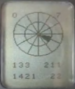
The preset for detecting the sound of gunfire (small arms, mortar, artillery, rocket artillery) and overcoming the sound barrier by ammunition is always enabled. This feature allows you to determine the course direction of the source and its range by phase shift and triangulation, and also due to the Doppler effect (the sound of a bullet or a projectile). Sound patterns with a clearly defined sound wave front, such as a gunshot, a bump, a bang, a single knock, a sneeze, allow to determine with high accuracy the direction of the sound wave source and range (knowing barometric and climatic parameters for adjusting corrections to the constant speed of sound).
Exiting examples
The EARS® family of gunshot localization systems gives soldiers and military police the situational awareness necessary to respond instantly and accurately to hostile attacks to better protect themselves from snipers and other gunfire threats.[12]
The picture above shows an example of the user interface (click to open in a separate window, and then again to open in maximum quality and maximize):
- a red dot is visible on the compass field on the left side, indicating the azimuth of the shot source (16°)
- below left, a large Gunfire Locator icon is displayed that tells you the direction of the oncoming shot (11h), range to source (331yd), elevation (0°), caliber of ammunition (.300), and number of shots fired (19)
- below left on the navigation grid you can see the localization of the source of enemy fire (GPS coordinates of the target are available to other users as well)
- the same navigation grid shows objects identified with the help of IFF (transponder), SDRS and RDF (radio interception and direction finding), PCSR (passive radar), CVC (computer vision) - to make it easier to use the navigation grid there are layers and filters, as well as pop-up and audible tips
- in the window in the center, this target is not displayed in the priority list for this user because there are users who are closer to the target and for them it will be a higher priority - AI evaluates the probability of crossfire and optimizes targets
Brief of assistance apps functionality
Here we briefly describe the functionality of the apps. You will find a more detailed description of the applications on their main articles pages. See the links below.
FA (Firing Assistance control)
![]() →redirect Main Article: Firing Assistance Control, Night Vision, Digital Sights
→redirect Main Article: Firing Assistance Control, Night Vision, Digital Sights
Features
The application includes:
- capture and track up to 10 targets simultaneously (uses Computer Vision Control)
- ballistic calculator (uses several applications at the same time, including Computer Vision Control)
- aiming assistant for all types of aiming devices
- fire spotter (uses Computer Vision Control)
- target designation history
The application is launched manually as a widget at the top of the CAM app window when one of the FA presets is enabled, at the same time the OD (Computer Vision Control) preset is automatically launched.
Presets:
- GF (Fire on ground fixed targets)
- GM (Fire on ground moving targets)
- AM (Fire on aerial moving targets)
- MF (Mountain fire on fixed targets)
- MM (Mountain fire on moving targets)
Ballistic calculator
The ballistic calculator for each target calculates the ballistic trajectory at a distance based on 20 parameters for a static and moving target (the display can be customized):
- TYPE - weapon type (saved in profile), incl. muzzle velocity (MVmph/kmh), zero range (ZRft/m), bore height / sight hight (BHin), zero hight (ZHin), zero offset (ZOin), SSF elevation (SSFe), SSF windage (SSFw), EclckMOA/MIL and WclckMOA/MIL, rifle twist rate (RT), rifle twist direction (RTd), calibrate muzzle velocity (CalMV), calibrate DSF (Drop Scale Factor) (CalDSF)[13][14]
- AMMO - ammunition type (saved in profile), incl. manufacturer's ballistic coefficient (BC), drag curve / drag model (DM) (G1, G7, custom), bullet weight (BWgr), bullet diameter (BDin), bullet length (BLin)
- TRNGyd/m - target range (no laser rangefinder[15][16])
- SLHft/m/x° - sighting line height, a negative value indicates a downhill shot
- ALTBft/m - altitude barometric, the vertical distance associated with given atmospheric pressure; an accurate reading depends on correct initial barometric pressure input and stable barometric pressure while measuring
- BPinHg/mmHg - barometric pressure, the local station (or absolute) pressure adjusted to mean pressure; an accurate reading depends on a correct altitude input and unchanging altitude while measuring
- RH% - relative humidity
- AIRT°F/°C - air temperature
- DoFx° - direction of fire, course angle to the magnetic pole for the Coriolis effect
- LATx°y'z'' - latitude, horizontal location on the Earth's surface, negative values are below the equator
- WDIRhrs/x° - wind direction from (incl. crosswind, headwind, tailwind - components of the full wind)
- WINDmph/kmh - wind speed (time average, last 2 measurements, manual entry of min and max, last measurement from 2 different impellers, last measurement from external device)
- AIRUPmph/kmh - upward air flow velocity (incl. dynamic upward flow and convection air flow), takes into account time of day, season, temperature, slope curvature and height, measurement history, weather satellite data
- DAft/m - density altitude[17], the altitude at which the density of the theoretical standard atmospheric conditions (ISA) would match the actual local air density
- DPT°F/°C - dew point temperature[18], the temperature at which water vapor will begin to condense out of the air
- HSI - heat stress index, a calculated value of the perceived temperature based on temperature and relative humidity
- SPinHg/mmHg - station pressure (absolute pressure), the pressure exerted by the atmosphere at the location
- WBT°F/°C - wet bulb temperature (psychrometric), the lowest temperature that can be reached in the existing environment by cooling through evaporation, wet bulb is always equal to or lower than ambient temperature.
- WCH°F/°C - wind chill, a calculated value of the perceived temperature based on temperature and wind speed
Displays 16 ballistic calculation reference data (display can be customized):
- ToFs - time of flight
- RemVfps/mps - remaining ammo velocity
- Mach - remaining ammo velocity in Mach units
- Rtrnsft/m - transonic range is the distance traveled by the bullet before it slows to transonic speed (Mach 1.2)
- Rsubft/m - subsonic is the distance traveled by the bullet before it slows to subsonic speed
- RemEft-lbf/J - remaining energy
- SpnDMOA/MIL L/R - spin drift (gyroscopic drift)
- CIA - cosine of the inclination angle to the target
- DroMOA/MIL - ammo true drop, the total drop the bullet experiences from its highest point in flight
- Trcein/cm - trace is the height above the elevation solution where the trace of the bullet will be most visible
- MaxOin/cm - maximum ordinance, height above the axis of the barrel that a bullet will reach along its flight path
- MaxORft/m - range at which the bullet will reach its maximum ordinance
- AerJ - aerodynamic jump is the amount of the elevation solution attributed to aerodynamic jump
- VCorMOA/MIL U/D - vertical Coriolis effect is the amount of the elevation solution attributed to the Coriolis effect
- HCorMOA/MIL L/R - horizontal Coriolis effect is the amount of the windage solution attributed to the Coriolis effect
- SPDmph/kmh - the speed of a moving target, a negative value indicates a target moving leftAdditionally for other presets:
- additionally for presets GM and MM calculates the angular velocity for uniform target movement, measurement of the distance to the target, the course of the target movement and indicates corrective lead corrections
- 20. LEAD MOA/MIL L/R - the horizontal correction needed to hit a target moving left or right at a given speed
- additionally for the AM preset, it calculates the angular velocity, the change in azimuth and determines the nearest probable trajectory with the designation of corrective lead corrections
- additionally for the MF preset, takes into account more complex parameters for calculating a ballistic trajectory in mountainous and desert areas based on landscape assessment, a steeper line of sight (sightline hight), temperatures, estimates of air updrafts and mirage effect, shot history
- for the MM preset as above plus additionally calculates the angular velocity and indicates the lead corrections
Using the ballistic calculator
- the user aims the reticle crosshairs (point of impact) at the intended target and locks the target manually, or the target is locked automatically using Computer Vision and the list of targets is displayed at the bottom of the horizontal list
- the current target is in the middle, on the left - the history of target designations, on the right - the next targets
- the name of the targets has a color in accordance with the rules of the IFF app
- if several targets are displayed in the window at the same time, they are marked with numbers, as in the list of target designations below
- the user sees in the interface and can make manual changes (input field) to the parameters of the ballistic calculation
- the application displays the aiming point (inner diameter 2MOA, outer diameter 5MOA) taking into account corrective amendments on the reticle relative to the crosshair with a scale in the form of digital data (Eunit and Wunit) MOA/MIL (true minute of angle/miliradian)
- separately displays the numerical values of the corrections: Elevation and Windage:
- EU/D and EclckU/D
- W1L/R - average measured wind speed and W1clckL/R
- W2L/R - maximum measured wind speed and W1clckL/R - so that you can manually make these corrections for the telescopic sight (the user must input the number of clicks needed to adjust the point of aim one TMOA or Mil, based on the turrets of their scope)
Using the aiming assistant
- when using Red Dot Sights or Holographic Sights (both eyes open), the user visually combines:
- target outline
- position of the aiming point (subject to amendments)
- sight dot (Red Dot diameter typically 2-5 MOA is the same as the size of the aiming point of the application) thus shifting the sight dot (line of sight) to hit the target at the crosshair point (point of impact) as on the screen of the device[19][20][21]
- when using non-digital sights, the sight glass (reticle/dot) must be raised about 2.5 inches above the eye (using an adapter to the standard picatinny rail) so that the line of sight matches the line of vision of one of the two cameras
- if the sight does not have a night vision function, it is recommended to use camera modes: SWIR, SLV, MXV2, MXV4
- if the sight has a night vision function, it is recommended to use the FHD camera mode
- if desired, the user can additionally turn on the adjacent central screen (CLW or CRW) with a different camera mode
- when integrated with a digital sight, the application immediately displays on the screen in the form of a yellow diamond the sight line of the digital sight, which must be aligned with the displayed aiming point
- default colors: reticle - black, aiming dot - azure, digital sight line of sight - yellow
- colors are user configurable for ambient light level and camera mode
- if the lower part of the mask is used, then its protruding elements (air filters) will interfere with the standard putting the rifle to cheek while aiming, at the same time, when using an adapter to increase the height of the sight, with the usual butt position with emphasis on the shoulder and the vertical position of the rifle, more comfortable head posture with less neck bending during firing
Fire spotter
- evaluates the shot by sound and compares the dynamics of the image within the radius of the crosshair
- additionally, the voice assistant asks the user to confirm that the target has been hit in order to determine whether to proceed to the next target or make an adjustment
- evaluates ballistic calculation inaccuracies in case of a miss and offers the user corrective corrections
- takes into account the history of shots and provides quick access to the history for the user
Circular Error Probable
In the case where the hit offset of the ammo is not known for correction, the strategy of the battleship paper game is applied. It is assumed that the aiming was done exactly in the center of the rhombus (aiming point), then depending on the weighting factors of the ballistic calculation, the offset from the primary aiming point is calculated depending on the history of the CEP (circular error probable). For example, the most influential factor is wind, for the second attempt for the offset this factor will be selected as a priority. This hypothesis should be tested experimentally.
Types of weapons and ammunition
- no restrictions for saving weapon and ammo profiles (unlike other manufacturers for different models)
- suitable for all types of small arms and grenade launchers where a ballistic trajectory is used (without jet thrust and gas generator)
- the capability of using the function for ballistic calculation and use for mortar fire is being investigated
- AM (Fire on aerial moving targets) preset is designed primarily "as an anti-aircraft gun on the ground" against drones at altitudes up to 1000 yards and with increased range against aircraft at altitudes up to 2000 yards including machine guns M2E2 / M2A1[22][23], M240B / M240L / Barrett 240LW[24], M249[25], M134 Minigun[26], ХМ250[27], MG5[28], M27[29][30]
- the capability of using for firing from a helicopter is being investigated
- the capability of using the function for remote control of MANPADS (a man-portable air-defense system)[31] (RBS 70/90[32], Javelin[33]) on a robotic turret - Lightweight Multiple Launcher (LML) is being investigated
Options and integrations
- Continuous Wind Capture (perspective function) at the top of the mask, it is possible to install 2 compact impellers on a turntable (increased accuracy in measuring wind speed and direction, hands free), which unfold by a spring mechanism and lock when folded, measurement intervals are set by the user
- for ballistic calculation at distances up to 5500 yards, integration with a portable weather station via Bluetooth is possible, for example, Kestrel 5700X Elite with LiNK[34][14][35] (LiNK Wireless Dongle connected to the mask top USB port), Garmin Foretrex 701 and GARMIN tactix Delta Solar Edition[36][37]
- as an option, other anemometers can be used to measure wind speed and direction, or the measured data of one user can be transmitted by other users within the P2P network
Related services
- when using digital sights, the sight line may be outside the field of view of the device's camera with a given magnification - in this case, thanks to the sensors of the digital sight, indicators appear on the screen in which direction the sight line needs to be shifted
- a list of detected and hit targets is entered as an auto task with characteristics and photo confirmation for further analysis
- all shots can be automatically entered as a completed auto task for greater detail
- operational history of shots is available in the app window
- detailed shot history available in the TSK app
- the FA app can track the ammunition stock and notify the user, as well as to the BMS (Battlefield Management System) analytical center, about the current stock of ammunition
- in accordance with the additional terms of reference, the algorithm, when capturing targets, can independently set priorities for targets
Capability to make fire corrections at night and hit small low-flying aerial vehicles
At dusk and at night (also dirung the day), in fog, smoke and dust, and when shooting at aerial targets, it is advantageous for the sniper and machine gunner, as well as any other shooter, to use tracer bullets, which, however, demask the shooter. Without the use of tracer bullets it is impossible to make corrections. To hit small low-flying aerial vehicles at an altitude of 60 ft or more in darkness, smoke, dust, fog, bad weather conditions is a very difficult task, especially if it is a small drone less than 8 in. To help comes mixed vision in HDR / SWIR / LWIR range, which help to track the target more clearly and see the trajectory of hot bullets in the long-wave infrared range.
The resolution of the Lepton 3.5, 160x120px, 57°, with shutter LWIR sensor makes it impossible to see a sharp image, much less use a digital zoom. Therefore, folded design technology for camera lenses solves this problem. For example, an area of the sky can be optically zoomed in and capturing the image without zooming to the sensor with additional post-processing by means of Computer Vision allows you to see the contours of the object for reliable aiming.

CPU load balancing is also necessary in this case in order to process streaming video at a sampling rate of at least 240 fps. This will allow you to see the trace of fast-flying (660-900 meters per second) bullets and projectiles to be able to correct aiming.

The video capture model is as follows. The image at 240 fps arrives at the LWIR sensor, bright pixels are processed by the preprocessor, then encoded (a temporal compression) at 30 or 60 fps, preserving motion details. Images on other HD, HDR, SWIR matrices are captured initially at 30 or 60 fps. The preprocessor performs tasks of object extraction (a sampling) by means of Computer Vision at a rate of 6 fps and then object detection. Then postprocessor performs layer-by-layer addition of video streams and real-time (30-80 ms delay) processing at 30 to 60 fps for playback in the interface window: source signal + fire trace image + Computer Vision markers.
See more About video and audio encoding and compression[38]
Machine Learning tools are also applied to effectively engage an aerial target. Namely, a probabilistic preemption model is calculated for target designation when firing at complex trajectory aerial targets.
Both functions of this technology can destroy aerial targets in the form of micro, mini, medium and large drones at altitudes up to 1-2 miles.
Interface examples
The picture above shows an example of the user interface (click to open in a separate window, and then again to open in maximum quality and maximize):
- the window in the center displays the search and target designation view of the FA system
- SWIR camera sensor view, 5x zoom, reticle with MOA, reticle size of one reticle division 13.29 in is enabled for this display
- actual ballistic calculations are displayed on the left and right sides of the screen
- bottom displays captured targets in individual sequence for each user - target priority is formed by AI based on such parameters as: user's proximity to the target, crossfire avoidance, target type and armor protection, target speed, user's ammunition stock and type, type of available weapons
- Fire Assistance will assist with target capture and aiming, while AI will allow smart target distribution (target selection and prioritization, fire correction) between multiple users, so that you don't try to hit one target at the same time, while no one is trying to hit another target at the moment
- targeting correction values are shown at the bottom for each target
- targets are displayed in color according to the IFF classification (in this case, the user can see that the targets are civilian objects, and this is also indicated by the large icon on the right "Warning! Civilians")
- objects in the search and target designation window are identified by the CVC (Compter Vision Control) system - the user can select an object of interest and get more detailed information in the context window on the right side of the screen
- the aiming line including corrective adjustments is shown in the form of a yellow rhombus
- the aiming line of the digital sight is indicated in the form of an azure circle with two crosshairs
- CVC system tracks the hit on the target by characteristic signs (point of entry, dust cloud, deformation, spark, etc.), as well as tracking with LWIR sensor image capture technology at high frequency (trajectories of hot bullets and projectiles) - in case of an inaccurate hit in case of precise aiming, corrective corrections are calculated again; in case of inaccurate aiming - remain unchanged;
- shot history for each target is stored in memory and displayed as a static image with a cloud of hit points
Facts. US forces have fired so many bullets in Iraq and Afghanistan - an estimated 250,000 for every insurgent killed - that American ammunition-makers cannot keep up with demand.[39]
Since WW1, WW2, Korean War, Vietnam War, operations in Iraq, Afghanistan and Syria, the amount of ammunition expended per target hit has been increasing. This is primarily due to harassing fire tactic, increased rate of fire, and increased fire density. Plus ammunition expended during training and lost during transportation. Whereas in the case of artillery ammunition stats 8-11 artillery shells per killed enemy. To hit 75 percent of the targets in an equipped enemy platoon position, 1,250 high-explosive shells are required. This equates to 60 rounds per person. The main development goal is to increase the proportion of guided munitions, in the case of small arms the main goal is to increase accuracy through training and electronic assistance.
SPOT (LED Spotlight settings)
![]() →redirect Main Article: LED Spotlight
→redirect Main Article: LED Spotlight
Features
The application starts when you turn on one of the modes in the SB (Status Bar). Does not start by default.
Capabilites:
- lighting in the near radius up to 10-30ft in front of the user with different intensity depending on the tilt of the head (super bright LED with reflector located at an angle of 45°)
- strobe mode[40][41]: used as Strobe Weapons[42][43][44][45] - effectively turn off the enemy's peripheral vision, cause disorientation and indecision, allowing the user to change position; do not allow the enemy to accurately aim and conduct effective return fire - during an assault in twilight and darkness, fading mask screens and camera visibility protect military personnel, allowing you to win a second, two or even more enemy inactivity
- SOS mode: used to be able to locate the user for medical assistance and evacuation
- when the full stealth mode FULL (STM) is on, the user will not be able to turn on the flashlight
- in power saving mode, the intensity will be reduced automatically or automatic shutdown will occur
- fine adjustments are made in the LED Spotlight settings - SPOT app
Interface examples
Insert picture for example
RPAC (Drone RC)
![]() →redirect Main Article: Drone RC
→redirect Main Article: Drone RC
Features
- remote control of different models through a single built-in controller (land, waterborne and aerial drones)
- interception of control of enemy drones (premature activation of ammunition drop, forced landing)
The application for remote control of RPA, UAV in accordance with the communication protocol and functions provided by the manufacturer for integrators.[46] The principle of FPV (First Person View) is used, when the drone operator uses a screen located on his head. Includes manual remote control via RF signal, automatic commands of this model, AI remote control model. Integration is configured in the menu section of the DVC app.
Streaming video and photos are transmitted over a radio channel (4.2-6.8 GHz) and recorded on a solid-state drive (SSD).
The software algorithm allows to avoid collision with obstacles.
The application window additionally uses CVC (Computer Vision Control) functions to detect and recognize objects, movement, people, face recognition, flashes, smoke and heat (if the drone's camera has an LWIR sensor) trace. Additionally, a software zoom in and zoom out with image interpolation is used to improve the quality and highlight the contours. Detected objects are displayed below, indicating their type (car, tank, helicopter, drone, person, etc.), speed, azimuth, altitude, GPS coordinates, course destination and size.
Multiple users can receive the drone's camera image. Drone control can be transferred from one user to another, incl. can change the source of the RF signal and the characteristics of the "home" for the drone during the flight.
The application is started manually.
Joystick and buttons control
The software joysticks located below the central windows are used. 2 fading pads, left and right: CWJP and CWBP. 2 joysticks and 10 buttons, incl. 2 buttons are multifunctional. The left area is responsible for controlling the altitude (Z), rotation around the vertical Z axis, camera tilt, zoom in and zoom out, camera modes. The right area is responsible for movement in the horizontal plane (X and Y), take-off, landing, automatic return (to the RF signal source or to the take-off geo-position), automatic following mode (following the RF signal source, following the user, following the specified object).
To control software joysticks, the HT (Hand Tracking System) app is used .
Remote control is carried out using the navigation reticle in the app window. When using only one surveillance camera, flight control can only be carried out according to navigation indicators. Key pointer:
- pitch
- roll
- horizon line
- course (azimuth)
- altitude
- speed (horizontal, vertical)
- distance from home (signal source or user)
- battery charge
- received and transmitted RF signal level (Rx, Tx)
- GPS signal level
- camera tilt angles
- camera mode and shooting options
- free space on SDD
Head tilt control with one joystick
To control the altitude (Z) and rotate around the vertical Z axis, the user can use the tilt of the head forth or back and turn the head left and right. After returning the head to its original position, the joystick position is 0.
To control along the X-axis (drone movement to the right and left), the user can use the left-right head tilt. To control along the Y-axis (moving the drone forward and backward), the user can slightly move the head back and forth.
The user can set up part of the control functions using the built-in joystick and buttons A, B, A+B, C, D, C+D, +/- on the left, +/- on the right.
Control with voice commands
With the TESS voice assistant, the user can remote control all functions with their voice.
Complex commands and automatic tasks
- Start mission, Pause mission, Stop mission - autonomous execution of the mission set through the NAV app (the control RF signal is not transmitted so as not to unmask the user; the RF signal from the drone with the data stream can also be turned off)
- Follow me, Follow target - following the user or the detected target at a safe (variable) altitude (control RF signal is not transmitted)
- Circle around me, Circle around target - move around the circle while keeping focus (control RF signal is not transmitted)
- other commands and AI control options
Integration
- configurable in DVC app
- drone categories: tricopters, quadcopters, hexacopters, octocopters, fixed wing drones
- drone classes: micro, mini, medium, heavy, super heavy
- ammunition drop system (most often, unguided hand grenades and mini-bombs)
Open source examples
Interface examples
Facts.
RBRC (Robot RC)
![]() →redirect Main Article: Robot RC
→redirect Main Article: Robot RC
Tasks Summary
| Missions | Fire Team | Force Recon - ISR | Light Armored | Scout Sniper | Low Altitude Air Defense | Helicopter - RPA | Artillery -Mortar | Combat Engineer | Flight Deck - Hull | Special Ops | SIGINT - EW | Medical Service |
|---|---|---|---|---|---|---|---|---|---|---|---|---|
| Intelligence (INT) -
Surveillance (SURV) - Reconnaissance (Recon) |
• Ambushes• RECON• SIGINT | • Ambushes• RECON• SIGINT | • Ambushes• RECON• SIGINT | • RECON• SURV• SIGINT | • SURV | • | • Crew Suppport (charging, cleaning) | • | • | • Ambushes | • SIGINT | • |
| Direct Action (DA) | • Forced entry | • Forced entry | • Forced entry• Gunfire Spotting | • Gunfire Spotting | • | • | • Gunfire Spotting | • | • | • Forced entry | • | • |
| Communication | • | • | • | • | • | • | • | • | • | • | • | • |
| Counter-Terrorism | • | • | • | • | • | • | • | • | • | • | • | • |
| Counter-Narcotics | • | • | • | • | • | • | • | • | • | • | • | • |
| Explosive Devices | • EOD• IED• Booby-Trapped Areas | • | • | • EOD• IED• Booby-Trapped Areas | • | • | • | • EOD• IED | • | • | • | • |
| Hostage Rescue | • | • | • | • | • | • | • | • | • | • | • | • |
| Combat Rescue | • | • | • | • | • | • | • | • | • | • | • | • |
| Casualty Evacuation (CASEVAC) | • | • | • | • | • | • | • | • | • | • | • | • CASEVAC |
| Transportation | • Carrying• Machine Gun | • Carrying | • Carrying | • | • | • | • | • | • | • Carrying | • | • |
| Site Security | • Patrolling | • Patrolling | • Patrolling | • | • | • | • | • | • | • | • | • |
| • | • | • | • | • | • | • | • | • | • | • | • | |
| • | • | • | • | • | • | • | • | • | • | • | • | |
| Detainee Riots | • | • | • | • | • | • | • | • | • | • | • | • |
Features
Universal Controller - High Definition (UC-HD) is a common controller that commands safety-critical unmanned assets such as large, high-speed unmanned ground vehicles (UGV) and unmanned aerial systems (UAS).
UC-HD has been developed with the wealth of knowledge in controlling large, high speed, and/or safety critical unmanned systems. UC-HD is compatible with existing, fielded route clearance unmanned ground vehicles (U.S. Army REF Minotaur), medium sized unmanned ground vehicle (TALON®), small unmanned ground vehicles, and Group 1 UAS platforms. UC-HD is compliant to emerging program requirements.[49]
Benefits:
- ARHUDFM Embedded
- Intuitive Controls
- Modular
- Adaptable
- Reconfigurable
Interface examples
FTRC (Fire turret RC)
![]() →redirect Main Article: Fire Turret RC
→redirect Main Article: Fire Turret RC
Features
Interface examples
UVRC (Unmanned vehicle RC)
![]() →redirect Main Article: Unmanned Vehicle RC
→redirect Main Article: Unmanned Vehicle RC
Features
Interface examples
VM (Virtual mentor)
![]() →redirect Main Article: Virtual Mentor
→redirect Main Article: Virtual Mentor
Features
The VM app is started manually as the VM tab of the MMD app group window (other tabs: REC, PLAY, TRSL). The application is necessary for cases of remote more qualified assistance, monitoring the training process and correcting errors in real time. A video conferencing app with two or more persons, including different networks, which allows to remotely exchange data streams with video, voice, text and file sharing. Since the user is not in front of the camera, instead of a video with him in the app window, the following are used:
- user camera view
- drone camera view
- user static avatar (photo)
- user AI-based virtual avatar (like in Apple Vision Pro, Synthesia and many other apps)[50][51]
Where it can be used
- Care Under Fire
- remote mentoring by one or more qualified physicians
- repair and maintenance mentoring
- instructor during training and tactical exercises in L-STE (Live-Synthetic Training Environment)
- personal mentoring during field tactical exercises
Open source examples
Interface examples
Insert picture for example
TRSL (Translater)
![]() →redirect Main Article: Translater
→redirect Main Article: Translater
Features
The application is started manually. Translation in both directions, incl. converting of the user's voice into text > translation into the language of the enemy or civilians > playback in the target language through the loudspeaker and headphones.
AI-based text translation app.
Open source examples
- DeepL
Interface examples
Insert picture for example
NOTS (Notifications)
![]() →redirect Main Article: Notifications
→redirect Main Article: Notifications
Features
The app starts in startup mode. The app shows and sounds other applications' notifications and system messages to the user.
Open source examples
Interface examples
Insert picture for example
TIPS (User tips)
![]() →redirect Main Article: User tips
→redirect Main Article: User tips
Features
The app starts in startup mode. The app is based on machine learning and incorporates best practices from many users. Depending on what applications the user is using, this app helps to save valuable time and make the best decision considering many environmental factors, mission, remaining resources, available threats, and availability of resources from other team members or other domains. Works autonomously without constant connection to BMS, L-STE systems. AI-based app.
Open source examples
Interface examples
Insert picture for example
VBS (Vitals Body sensors control)
![]() →redirect Main Article: Vitals Body Sensors Control, Body Sensors
→redirect Main Article: Vitals Body Sensors Control, Body Sensors
Features
The application includes:
- continuous monitoring of 7 groups of vital signs
- warning system about the presence of dangerous and critical conditions of the body
- user notification system, incl. recommendations
- monitoring log
- Care Under Fire system[52][53]
- Resuscitation on the Move system[54][55]
The application runs in the background when you turn on one of the presets and is available in the RQM (Right quick menu). Does not start by default.
Presets:
- WRK (Workout mode)
- displays tips for the user in case of many unwanted risks: bradycardia, tachycardia, arrhythmia, hypothermia, hyperthermia, hypoxemia, hyperventilation, hemorrhagic shock, etc.
- when a dangerous level of indicators occurs, displays a message to the user and sends an SOS message to the BMS (Battlefield Management System) analytical center
- keeps a log of monitoring states
- TRN (Training mode)
- additionally takes into account the duration of the session of training exercises and the capability of live fire training
- applies a programmatically set training mode for the use of automatic tourniquet
- TACT (Tactical mode)
- in addition to the above, if a dangerous level of acute massive blood loss occurs in one of the 8 sites protected by automatic tourniquets, it controls the "Care Under Fire" task for hemostatic and start emergency automatic infusion therapy (fluid resuscitation)
- if there is a risk of ventricular fibrillation, it automatically starts the defibrillation procedure under ECG control
- if necessary, start automatic pulmonary resuscitation using a pneumatic pump built into the design of air filters
- OFF
- does not monitor
When selected via RQM (Right quick menu), VUI (Voice user interface) via voice assistant, LMM and RSB (Left main menu and Right submenu), the application opens in a separate window showing real-time monitoring data, log history and log of messages and notifications.
The app:
- allows you to set up presets and integration with sensors through the DVC app
- allows accurate monitoring of vital signs in any position and on the move
- based on Machine Learning algorithms and medical scientific data, it assesses the presence of dangerous and critical conditions, in the event of which it sends messages and independently controls medical devices (automatic tourniquets, difibrillator, fluid resuscitation, pulmonary resuscitation)
- applies other AI methods
Monitoring
Vitals body data-driven monitoring including:
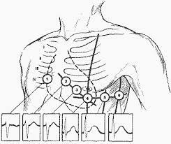
- HR bpm (ECG)[56] - assessment of rhythm and heart rate (pulse) in 12 leads, measured in 3 places on each arm and leg (sensors are built into 12 cuffs), as well as in 6 places on the chest (18 ECG electrodes instead of 10)
- NIBP mmHg (ART) - blood pressure (systolic / diastolic) non-invasively using 4 cuffs of the upper arm or thigh
- TEMP - body temperature (sensors are built into 12 cuffs)
- SpO₂ % - non-invasive method for monitoring the level of oxygen saturation in tissues (sensors are built into 12 cuffs); tissue oximetry method is based on the absorption by hemoglobin (Hb) of light of two different wavelengths (660 nm, red and 940 nm, infrared), which varies depending on its saturation with oxygen; the light signal, passing through the tissues, acquires a pulsating character due to a change in the volume of the arterial bed with each heartbeat; the pulse oximeter uses only light radiation and therefore is completely safe and has no contraindications
- ETCO₂ % - (capnometry) to measure the level of carboxyhemoglobin (COHb) and methemoglobin (MetHb), measured by the CO₂ sensor built into the mask airway obturator
- RESP bpm (RR) - Respiratory Rate, measured by a sensor built into the mask airway obturator
- HYDRL - using optical sensors built into the drinking system determines the amount and frequency of hydration by the user
- Glasgow test[57] to assess the degree of shock
In contrast to monitoring patients in the clinic, this sensor system provides for monitoring while standing, sitting and on the move, in the event of an emergency for an effective resuscitation process and first aid, incl. with loss of limb and acute bleeding. Therefore, it is important to get information from more sensors in different places in order to monitor.
The most important goal of developing this subsystem within the ARHUDFM platform is to monitor the physical and psychological state of military personnel during intense physical training, field exercises and tactical missions. The primary task of the subsystem is to timely detect dangerous and critical conditions in order to report them to the BMS (Battlefield Management System) analytical center, other nearby users and the user himself. The second most important task is the immediate "Care Under Fire" in critical conditions, if medical assistance cannot be provided in a timely manner within the first minutes. The third most important task is to assist rescue teams in the search for the victim and his evacuation.
Continuous monitoring capabilities
ECG in 12 leads, monitoring of body temperature, respiratory system and drinking system allows to:
- determine the degree of fatigue and dehydration
- stress levels and shock
- identify limit levels and duration of exercise that is safe for health
- identify random anomalies, arrhythmias, latent diseases or the initial stages of diseases
- timely diagnose crisis medical symptoms
- instantly respond to blood loss and give a command to trigger one or more (8) limb auto tourniquets
- immediately respond to cardiac arrest[58] (more precisely, to ventricular fibrillation (95% of cases) and heart failure in the presence of bioelectrical activity, causes hypoxia) and immediately begin resuscitation, including defibrillator discharges of different power (a short high-voltage pulse that causes a complete contraction of the myocardium)
- start and control automatic pulmonary resuscitation with the help of 2 pneumatic pumps built into the design of the air filters
- start and control automatic emergency injection (worn behind the back in an elastic vest) of an infusion solution (Fluid Resuscitation) through a pre-implanted venous port-system (for example, into the right subclavian vein, for several years, up to 2000 punctures with a special needle)[59]
- instantly send an alert message for help within the unit, domain and between domains, including position and vital status, incl. when identifying the approach of the evacuation group, it turns on the light mode "SOS"
Optional extension of the monitoring system
Optionally, the monitoring system can be supplemented and is capable to automatically control:
- 8 automatic tourniquets on the shoulders, forearms, thighs and shins to stop bleeding under ECG control
- magnetic mixing valve for automatic fluid resuscitation in acute massive blood loss
- ventricular defibrillation under ECG control
- pulmonary resuscitation under the control of several sensors simultaneously
Sensor system and built-in defibrillator
The sensor system is integrated via Bluetooth and includes installation locations (cuffs):
- 2 wrists (including checking the pulse when the auto tourniquet is started higher)
- 2 forearms (including auto tourniquet)
- 2 arms (including auto tourniquet)
- 2 ankles (including checking the pulse when the auto tourniquet is started higher)
- 2 shins (including auto tourniquet)
- 2 thighs (including auto turnstile)
- a perforated elastic chest belt with one strap over the right shoulder includes built-in reusable electrodes of the Holter ECG monitor in 12 leads[60][61] and at the same time a built-in difibrillator (analogous to WCD / ICD[62][63]):
- 4th intercostal space on the right side of the sternum
- 4th intercostal space on the left side of the sternum
- 5th rib along the left parasternal line
- 5th intercostal space along the left line of the middle clavicle
- 5th intercostal space in the axillary line in front
- 5th intercostal space in the mid-axillary line
Automatic stop of acute massive bleeding (auto tourniquets)
- the tourniquet is applied in case of massive bleeding according to the "high and tight" principle
- if it's not done in a timely manner, a person can die within 2-3 minutes
- after applying the tourniquet, the victim should be examined by a physician as soon as possible
- a person can wear the tourniquet without loosening, safely up to 2 hours and relatively safe from 2 to 6 hours
- the tourniquet must not be loosened, it is dangerous for health and life, because loosening the tourniquet can lead to the resumption of critical bleeding
- bleeding when applying a tourniquet stops as a result of muscle compression
- critical bleeding is not divided into arterial and venous, the tourniquet is always applied above the wound
- places for installation of auto tourniquets: shoulder, forearm, thigh, shin - in each case in the upper part
- limb circumference / tourniquet width x 16.67 + 67
- it is necessary to control the absence of weakening every 5-10 minutes. automatically measuring pulse and limb temperature on both sides of the tourniquet
- references - original tourniquets CAT, NAR, LEAF[64]
Automatic fluid resuscitation
Fluid resuscitation is performed with a magnetic mixing valve and a spring pocket for infusion bags that pressurizes the fluid. Fluid resuscitation is required in case of acute massive blood loss under BP and ECG control, e.g. more than 20% of circulating blood volume[65], according to the TASH (Trauma Associated Severe Hemorrhage) score scale[66][67], through pre-connected via a port-system to the right subclavian vein, using infusion bags with plasma substitute ("small volume resuscitation"), anticoagulant and possibly other solutions (all small volumes, fluid resuscitation depends on the complex of vital signs and the individual reaction of the organism).[68][69]
Automatic external defibrillation (AED)
VBS app will instantly evaluate several parameters and, if necessary, automatically stop blood loss in the limbs, and immediately start other types of "Care Under Fire" - pulmonary and cardiac resuscitation.[70]
Because the time between cardiac arrest and defibrillation is directly related to survival, a therapeutic shock must be delivered within minutes of the event to be effective. With every minute without treatment, the patient's chances of survival are reduced by 7-10%.
Shockable rhythm, unconscious patient, circulation ineffective:
- ventricular fibrillation
- ventricular tachycardia without pulse
"Synchronized" rhythms, the patient is often conscious but hemodynamically unstable (ECG-controlled, synchronized with the R wave)[71]:
- atrial fibrillation
- atrial flutter
- atrioventricular nodal reentrant tachycardia (AVNRT)
- ventricular tachycardia with pulse (patient is awake, stable blood pressure)
The user is alerted to the start of a treatment sequence, for example, by beeper signals and voice information. By simultaneously pressing the two response buttons on the monitor, the user can prevent unnecessary shocks while he is conscious. If the user does not respond, for example, because the user has lost consciousness due to arrhythmia or ventricular fibrillation in anticipation of cardiac arrest due to circulatory arrest, the gel is automatically ejected from under the defibrillator electrodes.[62][72]
Main causes of heart failure
The main causes of pulmonary and heart failure, acute tachycardia and life-threatening conditions[73][74]:
- contusion of internal organs
- blunt trauma and concussion of the heart and lungs
- acute bleeding more than 150 ml/min (decrease in systolic blood pressure less than 90 mm Hg and an increase in heart rate over 110 beats per minute with blood loss over 1500 ml / 30%, respiratory rate 20-30 breaths per minute, excited state)
- state of shock
Pulmonary resuscitation
Pulmonary resuscitation[75] (artificial ventilation of the lungs without intubation - CPAP, continuous positive airway pressure) is used with a small inspiratory volume (6-7 ml per 1 kg of body weight) with a moderate positive end-expiratory pressure (up to 5 mbar), especially in patients with traumatic bleeding, is required due to risk of developing respiratory distress syndrome.
How this system is implemented:
- the lower part of the mask contains 2 housings for HEPA-14 or ULPA-15 air filters, which, with a large area of filter material, creates resistance to air movement that a person does not feel even with a large volume of lung chambers and rapid breathing (for example, during intense exercise)
- in the pre-filter zone there is also a filling of activated carbon and the pre-filter itself
- together this filtration system protects the user with 99.9995% efficiency against dust, powder and many other harmful gases, aerosols, bacteria and viruses, and optionally against carbon monoxide (CO)
- centrifugal fans with electric permanent magnet synchronous motors (PMSM) with high torque (similar to those used in quadcopter rotors, medical and lab equipment) can also optionally be installed in the internal cylinders of the filter housings - the design turns into 2 fairly powerful and flexibly controlled ventilation devices with good performance (up to 30 l/min, up to 105 kPa, breath duration 1.2-4.4 s, alternate operation of two air pumps) [76]
- in case of a critical situation of respiratory arrest, instead of a medical air bag, which must be pumped manually by another person, the system will automatically start the electric motors, which, in turn, under the control of the ECG, pulse oximeter and other sensors, will provide the unconscious user with artificial lung ventilation for a long time
- filter system inlet check valves and double sealing (mask airway obturator and face seal) allow such a system to work efficiently
- the exhaust check valve, when the system is activated, uses a magnetic lock to prevent the loss of the created overpressure in the mask airway obturator at the moment of breath in
- of course, we are interested in the opinion of medical experts in the field of resuscitation, but technically we see no obstacles to implementing such a system - the history of the development of the problem of forced ventilation of the lungs and survival statistics prove this with facts
Perforated elastic chest belt
Includes pockets to accommodate (optional):
- front 6 electrodes with automatic ejection of electrically conductive gel (or reusable adhesive gel electrodes)
- 2 rear and 1 front automatic difibrillator electrodes (also with manual triggering for assistance)
- connecting cables
- 2 in the back to accommodate additional power supplies (4x12, max 48pcs LiMgCoAl 26650 3.7V 5500mah, ~ 1,065.6wh, 9.9 lbs / 4.6 kg)
- 1 infusion bags with plasma substitute 500-750 ml (at 2.14 ml/kg/h[77] equals 3-4 hours before arrival at the hospital)
- 1 or 2 infusion bags with anticoagulant and possibly also with other solutions, less than 100 ml
- connection system for automatic infusion therapy, connected to a port system previously installed in the right subclavian vein (under the skin)
- 1 drinking water bag for built-in drinking system, 3-4 lbs
Total weight without additional power sources and drinking water - less than 3 lbs
The use of the ARHUDFM platform reduces the overall weight of the gear by approximately 2 lbs.
Facts for comparison:
- we expect to at least halve the mass of additional power supplies (9.9lbs, 1.1kWh) within 3-4 years as battery technology advances
- technologies for cardiac monitoring, health monitoring using sensors, resuscitation on the move have been used for more than 10-20 years - with the help of modern components and technologies, we are capable to make them much more compact and lighter in order to give the military an additional chance to survive in a potentially extreme situation
- projected price of ARHUDFM is lower than the cost of one M1128 155 mm artillery shell (~$4000)
- a full kit of gear is 47% cheaper and 2 pounds lighter, but the difference in capabilities is huge
Conclusion
It seems to us that this is a serious problem, since with several wounded with acute massive blood loss, the medic (orderly) simply will not have enough plasma substitute to save lives until the moment of evacuation and delivery to the hospital (average 2-4 hours). The same goes for the speed at which the medic can start "Care Under Fire" and his ability to treat multiple casualties at the same time.
However, these systems not only change the rules of the game on the battlefield, but are also capable, compared to the equipment used today, to significantly increase the battery life of electronic equipment, provide communication and effectively save lives in emergency situations when time is counted by minutes, not hours. Nearly 18% of deaths can be avoided if help is provided by specially trained first responders within the first ten minutes, the so-called platinum ten minutes.
As a result, an integrated high-tech approach allows maintaining the high combat effectiveness of personnel and saving the effort invested in the training of each fighter. And most importantly - save the fighter's life![78][79][80]
Many published requests for innovation proposals from US, UK and EU defense agencies are focused specifically on improving the survival of soldiers during combat and the means of Care Under Fire. Therefore, our innovations are entirely in the general trend.
Interface examples
Insert picture for example
Brief of communications apps functionality
Here we briefly describe the functionality of the apps. You will find a more detailed description of the applications on their main articles pages. See the links below.
MSG (Messenger)
![]() →redirect Main Article: Messenger
→redirect Main Article: Messenger
Features
This application combines several components that can be selected through LMM (Left Main Menu) and RSB (Right Submenu), RQM (Right Quick Menu) or in the tabs of one of the elements already running in a separate window:
- IMSG ((instant messaging system)
- CHAT (multichannel chat)
- MAIL (eMail)
- SDR2 (SDR 2-way)
- ANTC (Antenna control)
Each additional element can be opened in the same previously opened window or in a separate window. Specified in the settings for the user.
Interface examples
Insert picture for example
IMSG (Instant messaging system)
![]() →redirect Main Article: Messenger, Instant Messaging System
→redirect Main Article: Messenger, Instant Messaging System
Features
The system consists of several groups of iconographic symbols. In many ways it resembles the system of road signs, which have a concise form and are perceived instantly, causing an appropriate reaction. Such a system is perceived much faster than a text or voice command. An example of this is the sign language used in special operations units. Also unlike the voice call session is much shorter, does not overload the communication line, small data packet is not demanding on the data rate, the digital data packet with the control notification of receipt always means only 2 states, that the message is received or not. No problem with message illegibility, lack of clarity in the message. No need to tell who is transmitting the message. This method itself is very concise and eliminates unnecessary information, thus relieving the communication channel and the attention of users. This communication system is particularly important for international contingents and during joint exercises.
The sender of the message by voice command (the user's voice is acoustically isolated from the surroundings by the obturator airway and the mask body) or by gesture informs: group or individual recipient (by alphanumeric code), command or command response (see example below), information for clarification (course, distance, quantity, reason, code, object name). By default, if no recipient is specified, each subsequent message is addressed to the same as the previous one. Also, as a general rule, if no clarifying information is specified, it is not transmitted. In this way, communication is further accelerated. Pronounced: <user> (<usergroup>) + <command> + <info>
The user who sent the message sees to whom the last message was not delivered. The interface shows the data of the users who have not sent a confirmation message back. The interface also shows the last messages received from users.
Some examples of voice commands in English used in the Icon Messaging System ("+i" where clarifying information is provided by default):[81][82][83]
| Notification | Reply | Command | Request | Report | ACP-131 Z-codes |
|---|---|---|---|---|---|
| Warning! Threat +i | Online | Total silence | Call <user> | Transmitting target coordinates +i | ZAL: Alter your wavelength. |
| Warning! Civilians +i | Standby | Cancel | Report | Fault report +i | ZAR: This is my .#. request (or reply). |
| Warning! Friendly forces +i | WILCO (will comply) | Cleared | Picture report | Injury report +i | ZDE *: Message ... undelivered, *.. |
| Warning! Gas +i | CANNOT +i | Recleared | Requesting command +i | Ammo report +i | ZEK: No answer is required. |
| Cell leader <user> | Clarify me | Disregard | Requesting support +i | Picture report +i | ZDG: Accuracy of following message(s) (or message ...) is doubtful. Correction or confirmation will be forthcoming. |
| Hurry Up | Done | Cover me by fire | Requesting evacuation +i | Monitoring report +i | ZEL: This message is correctionto message ... (transmitted by ...). |
| Rally Point +i | Check it +i | Follow me | Requestion medical aid +i | Motion report +i | ZET: Message ... has been protected andno further action by ... is required. |
| No info | Don't follow me | Requesting clarification +i | Radio monitoring data report +i | ZEV: Request you acknowledge message ... / Message (or message ...) is acknowledged. | |
| No connection +i | Dividing +i | Requesting comm channel +i | Meteo report +i | ZIP: Increase power. | |
| Target coordinates confirmed +i | Formation +i | Requesting target coordinates +i | ZOM: Delivery of this message by mail in lieu of broadcast permissible (to ...). | ||
| Target destruction confirmed +i | Find shelter | Requesting ammunition +i | ZUE: Affirmative (Yes). | ||
| Ready to fire | Take up defenses | Requestion radio scanning +i | ZUG: Negative (No). | ||
| Confirm | Take position +i | Requestion meteo report +i | ZUH: Unable to comply. | ||
| Negative | Change position +i | ZUJ: Stand by. | |||
| Do surveillance +i | ZWF: Incorect. | ||||
| Perform tactical reconnaissance +i | ZWG: You are correct. | ||||
| Watch out! Fire | ZWH: Try again. | ||||
| Charge +i | ZWI: Answer last question (or question ...). | ||||
| Apply disguise +i | |||||
| Freeze | |||||
| Go here +i | |||||
| Go away +i | |||||
| Keep distance +i |
See also the messaging system within the USMC on 217 page - Hand-and-Arm Signals ("Marine Rifle Squad").
Icon messaging system messages are displayed immediately without notification (in the RUW window).
Instant messaging system recognizes gestures and voice commands to send to group members or personally iconographic symbols, like road signs. Most often used in tactical tasks by assault units, reconnaissance groups and snipers.
Interface examples
Facts.
CHAT (Chat)
![]() →redirect Main Article: Messenger, Chat
→redirect Main Article: Messenger, Chat
Features
The application starts automatically in a separate window. The app window contains tabs for quick access to CHAT, MAIL, SDR2, ANTC apps. The app window can be maximized: 1:2 (vertically 2 adjacent windows), 2:2 (large window on the right, incl. 4 mini windows).
CHAT app:
- allows you to receive, send and forward messages to others, including those with a mandatory response request
- allows you to see chat subscribers with status (online, be right back, don't disturb, offline)
- allows you to see when the subscriber was online last time
- text messages can be generated using the STT (Speech-to-text settings) app and then voiced using VOVR (Voiceover settings)
- text messages can be generated by the TESS (Voice assistant)
- text messages can be entered via the virtual keyboard using the HT (Hand tracking system) or the joystick with buttons on the headphones ear cup
- short voice messages are less desirable and can be used in some cases as an exception
- messages may include multimedia data (photos, including screenshots, video, audio), digital data (measurements, RF scan results, CV & CA patterns, vector data, keys, etc.)
- messages may include a request or offer for real-time remote access to one of the user's cameras, incl. external cameras of drones, robots, digital sights
- messages may include a request or offer for remote access to application data NAV, PATH, IFF, SDRS, RDF, PCSR, RWRC, APAR, RFDD, EODD, CAM + CVC + FA
- messages are grouped into chats:
- one-to-one (there are two users in the chat)
- one-to-many (one user is in several chats)
- many-to-one (group chat with more than one user)
- many-to-many (cross-domain interactions, connections between chats that do not directly have the same connecting user, in particular, this is used in WGR (Workgroups), the AGILE principle is applied, the influence of the human factor is minimized, AI algorithms are used)
- flexible choice of channels for receiving and transmitting in accordance with the specified priorities and settings in the NET (Networks) app
- user notifications (flexible settings) about the number of unread messages, about the need for a response, about reading the sent message, about mentioning the user, about new messages in certain chats
- distributed display of quoting on 2 screens, so that in the chat it is easy to understand which message the user is responding to
- mention of the user that triggers the notification
- message importance status
- mark as a favorite message for quick re-search through the filter
- search in message history by keywords, author or mention, date and time
Notifications
In LMM (Left main menu) and RSB (Right submenu):
- in the upper right corner, a counter of notifications of messages requiring a response is displayed
- in the lower left corner, the number of unread messages is displayed
In RFS (Right features sidebar) in the list of chats for each chat icon:
- at the top, a counter of notifications of messages requiring a response is displayed
- below is the number of unread messages
Filters and sorting
- the list of chats is sorted based on the user (administrator) settings, by default:
- messages marked as important requiring a response turn the chat icon red and are shown at the beginning in chronological order
- messages that are not marked as important and require a response are colored in the chat icon in yellow and are shown after the red icons in chronological order
- chats with not require a response messages and consisting unreviewed messages are displayed in azure color after the yellow icons in chronological order
- the rest of the chats are displayed in the azure color below the above in chronological order
- to quickly filter messages from different chats marked as favorites, the "Favorites" icon is displayed in the RFS menu
- for the user to view the history of all sent and received messages, as well as their responses, the "My messages" icon is displayed in the chat list
- to scroll through the pages of the RFS menu with a list of chats (4 chats on one page of the list), arrow buttons are displayed or voice commands are used through the TESS voice assistant
Identification
- for identification inside icons for individual chats, the first letters of the first and last names plus the rank (variations are possible, callsign, etc.)
- an alphanumeric code is used to identify group chats (options with the image of animals, birds, insects, reptiles, musical instruments, movie characters or a unique callsign are possible)
Interface examples
Facts.
MAIL (eMail client)
![]() →redirect Main Article: Messenger, eMail Client
→redirect Main Article: Messenger, eMail Client
Features
Interface examples
Insert picture for example
SDR2 (SDR 2-way)
![]() →redirect Main Article: Messenger, SDR 2-way, Software Defined Radio
→redirect Main Article: Messenger, SDR 2-way, Software Defined Radio
Features
The SDR2 application is the software defined radio to have become a communications system standard for the U.S. Military[84]. As one of most versatile tactical radios, one four-channel SDR2 can simultaneously support voice and data satellite communication networks, Mobile User Objective System (MUOS) waveforms, Single Channel Ground and Airborne Radio Systems, HAVEQUICK, Mobile Ad Hoc Network (MANET), and other tactical, HF/VHF/UHF radios[85][86]. The SDR2 will offer to certify by the Joint Interoperability Test Command (JITC) to be compliant with the U.S. government’s UHF SATCOM.
- single 4-channel radio for the entire 2 MHz – 2 GHz band
- single point of control for entire HF/VHF/UHF/SATCOM system
- digital data transmission at fixed frequencies (DEFF)
- digital data transmission at hopping frequencies (DEFH)
- embedded AES Encryption
- reduced manpower requirements
- high reliability
- built-in test and antennas analyzer (ANTC)
- low life-cycle costs
- very low maintenance costs
- lower spares cost and inventory
Waveforms and frequency bands
| SDR Waveform | Frequency Band | Bandwidth | Modulation | Operative Scenario | Standard |
|---|---|---|---|---|---|
| Link-11 | HF 2-30 MHz | 3-24 KHz | USB, LSB, ISB | BLOS (Ground & Sky wave)
Data Modem [75-9600bps] |
|
| Data Modem WF | HF 2-30 MHz | 3-24 KHz | PSK, QAM | BLOS (Ground & Sky wave)
Data Modem [75-9600bps] |
MIL 188-110 B |
| ALE 3G WF | HF 2-30 MHz | 3-24 KHz | FLSU/FTM (or RLSU), BW0, BW1, BW2, BW3, Single-tone, 8PSK | BLOS (Ground & Sky wave)
HF Link Management |
STANAG 4538 |
| ALE 2G WF | HF 2-30 MHz | 25 KHz | 8FSK | BLOS (Ground & Sky wave)
HF Link Management |
MIL 188-141B |
| ALE 4G WB-HF WF | HF 2-30 MHz | 3-24 KHz | App. C compliant | BLOS (Ground & Sky wave)
WB Data Modem |
MIL-STD 188-110C |
| HF Modem WF | HF 2-30 MHz | 25 KHz | PSKs | BLOS (Ground & Sky wave)
Data Modem [70 .. 3600 bps] |
STANAG 4285
MIL-STD-188-110C |
| ANW2C,
UHF LOS, P25, WF40 (MANET WF), EPM WF |
VHF low: 30-88 MHz,
VHF high: 118-174 MHz, UHF: 225-512 MHz |
25 KHz | AM, FM, FSK, BPSK, SBPSK, QPSK, CPM | Ground Communications,
Ground-to-Air-to-Ground Interoperability |
AM Civil and Military Aviation (WB/NB)
FM Voice and Data (WB/NB) |
| VULOS | VHF low: 30-88 MHz
UHF 30-400 MHz |
25 KHz | AM, FM, ASK, FSK | Ground Communications,
Ground-to-Air-to-Ground Interoperability |
STANAG 4204 / 4205 |
| SINCGARS[87] | VHF 30-88 MHz | 25 KHz | FM, FSK | Ground Communications,
Ground-to-Air-to-Ground Interoperability |
MIL-STD-188-242,
MIL-STD-188-220, MIL-STD-188-241 |
| SATURN | UHF 225-400 MHz | 25 KHz | MSK | Ground-to-Air-to-Ground Interoperability | STANAG 4372 |
| SATCOM DAMA | VHF,
UHF 225-400 MHz |
5-20 KHz | TDMA DAMA PSK, CMP, FSK | Satellite Communication for BLOS link | MIL-STD-188-181A,
MIL-STD-188-182A, MIL-STD-188-183 |
| HAVEQUICK I/II | UHF 225-400 MHz | 25 KHz | AM | Ground-to-Air-to-Ground Interoperability | STANAG 4246 |
| ANW2C,
UHF LOS |
UHF: 225-450 MHz | 25 KHz | AM, FM | Ground-to-Air-to-Ground Interoperability | |
| SATCOM | 300-320 MHz UL /
360-380 MHz DL |
5-20 KHz | FSK, PSK, CPM | Satellite Communication for BLOS link | |
| UHF SATCOM | UHF SATCOM:
291-318.3 MHz UL / 243-270 MHz DL |
5-20 KHz | FSK, PSK, CPM | Satellite Communication for BLOS link | |
| VULOS,
SINCGARS[87], HAVEQUICK I/II, HPW, HPW IP, APCO P25, P25 OTAR Link-4A |
Narrowband:
VHF 30-225 MHz, UHF 225-512 MHz |
8.33,
12.5, 25 kHz |
AM, FM | Ground Communications,
Ground-to-Air-to-Ground Interoperability |
|
| High Performance Waveform (HPW),
HPW IP |
Legacy SATCOM:
RX 243-270 MHz, TX 291-318 MHz |
5 kHz,
25 kHz |
TDMA Capability (STC) | Satellite Communication for BLOS link | MIL-STD-188-181B,
MIL-STD-188-182A, MIL-STD-188-183, MIL-STD-188-181C, MIL-STD-188-183B IW Phase 1 |
| VULOS/P25 | Highband:
UHF 512-520 & 762-870 MHz |
AM, ASK, FM, FSK | Ground Communications,
Ground-to-Air-to-Ground Interoperability |
||
| ANW2C,
SRW |
Wideband:
225-450 MHz |
500 kHz,
1.2 MHz |
AM, ASK, FM | Ground-to-Air-to-Ground Interoperability | |
| UHF 762-870 MHz | 12.5,
25 kHz |
FM | |||
| ROVER III L-BAND RECEIVE | L/S-band:
1300-2600 MHz |
L-TAC | |||
| MUOS (WCDMA)[88][89][90] | MUOS:
Uplink: 300-320 MHz; Downlink: 360-380 MHz |
Ground Communications,
Ground-to-Air-to-Ground Interoperability |
MIL-STD-188-187 MUOS |
Net presets: unlimited
Frequency tuning: 5, 10 Hz
Transmission power: user programmable 250 mW to 5 W, 10 W SATCOM burst mode
Encryption: Type 1 encryption (suite A/B)[91], L3Harris Sierra II-based[92], NSA-certified TOP SECRET and Below[93]
Reprogrammable Voice and Data Security Options:
- AES[94] (Type 1 & 3; 128, 192, 256, 384 bits)
- Type 3 DES[95]
- KY-57/58 (VINSON)[96]
- KGV-10, 11
- KG-84A/C[97]
- KYV-5 (ANDVT)
- KY-99A
- KWR-46
- FASCINATOR
- HAIPE (PPK/ FFV)
- VULOS
- HPW
- TSVCIS
- Others as Required*
Software selectable choice of 5 antenna port connectors[98] (optional: 50 Ohm TNC[99], N[100], BNC[101]).
Electronic counter-countermeasures (ECCM)
ECCM is a part of electronic warfare which includes a variety of practices which attempt to reduce or eliminate the effect of electronic countermeasures (ECM) on electronic sensors. ECCM is also known as electronic protective measures (EPM), chiefly in Europe.
- Frequency hopping
Frequency agility ("frequency hopping") may be used to rapidly switch the frequency of the transmitted energy, and receiving only that frequency during the receiving time window. This foils jammers which cannot detect this switch in frequency quickly enough or predict the next hop frequency, and switch their own jamming frequency accordingly during the receiving time window. The most advanced jamming techniques have a very wide and fast frequency range, and might possibly jam out an antijammer.
- 4-channel simultaneous Tx / Rx sessions
This method is also useful against barrage jamming in that it forces the jammer to spread its jamming power across multiple frequencies in the jammed system's frequency range, reducing its power in the actual frequency used by the equipment at any one time. The use of spread-spectrum techniques allow signals to be spread over a wide enough spectrum to make jamming of such a wideband signal difficult.
- Polarization
Polarization can be used to filter out unwanted signals, such as jamming. If a jammer and receiver do not have the same polarization, the jamming signal will incur a loss that reduces its effectiveness. The four basic polarizations are linear horizontal, linear vertical, right-hand circular, and left-hand circular. The signal loss inherent in a cross polarized (transmitter different from receiver) pair is 3 dB for dissimilar types, and 17 dB for opposites.
- Radiation homing
Another ECCM practice is to use narrow beam antennas and dynamically track changes of another person location. Unlike omnidirectional and wide-beam antennas, which can be detected in their propagation path, narrow-beam antennas are less likely to direct a signal that will be detected by an enemy. This technology is available with SDA (software-defined antennas).
Advantages
- allows to send and receive messages without distortion and loss, incl. to helicopters, aircrafts and satellites, due to the predominant use of text (character) data, rather than voice messages - in this case, the text can be read or voiced on other user device
- significantly less traffic, which makes it capable to provide communications for each military person: soldier, Marine, airman, sailor, Coast Guardsman, and not just for team (squad / section, platoon, company, batallion, brigade, division, and other units) leaders, officers and commanders
- there are fewer restrictions on the number of configurable channels within the allowed radio frequency range (with different waveforms, modulations and polarizations), group and individual - 4 active connections (channels) can be supported simultaneously through different networks, if the number of active channels exceeds 4, they are polled in order queues
- one channel can be configured for fixed frequency and frequency hopping connection
- it is always possible to return, read or voice a previously received or sent message in a text (character) format, unlike a voice call
- thanks to the text (character) type of data, encryption is faster, at a significantly more complex level (data protection is many times higher) and requires less system load
- multimedia data transmission can be faster if they are transmitted to the cloud via a satellite channel and then sent a link to cloud repository, and only Computer Vision and Computer Audition digital vectors data are transmitted between ground stations and aircraft, i.e. result, not source material
- software-defined antenna allows you to receive and transmit simultaneously in several frequency bands, incl. UHF SAT and MUOS (WCDMA), while it is more difficult to detect radio session, because antenna uses highly narrow directional signals
Each user can act as a relay for messages of other users, if the free bandwidth of the channel allows (messages are queued).
Open source examples
Interface examples
Insert picture for example
CRPT (Cryptologic control)
![]() →redirect Main Article: Messenger, Cryptologic Control
→redirect Main Article: Messenger, Cryptologic Control
Features
The application for key management and encryption. The basic version offers a solution for AES: 128, 192, 256, 384 bits. An add-on for other encryption systems can be developed.
Interface examples
Insert picture for example
PTTH (PTT Headset)
![]() →redirect Main Article: Messenger, PTT Headset, Handheld Radio
→redirect Main Article: Messenger, PTT Headset, Handheld Radio
Features
The application starts automatically when you connect a 4-pin J11 NATO (Nexus TP-120, 1-ch) or 5-pin (Nexus TP-105, 1 ch + data)[102] or for L3Harris/Thales products: 5-pin / 6-pin ADF (1-ch: GND, SPK, PTT, MIC, EXP, EXT)[103][104][105][106][107] or 19-pin ADF (2-ch)[108][109][110] portable handheld & manpack radio headset cable. Also for ground / vehicular radio headset cable. Adapters are required to connect the following types of connectors: 6-pin ADF, 10-pin MBITR, FL5010 Icom, FL5030, FLX2, Kenwood and Baofeng Double 4-pin Connector, Motorola Double 4-pin Connector, Icom Double 4-pin Connector, L- Type 4-pin, 11-pin M15 Sepura, Motorola M12, Motorola M15, Kenwood Multipin, Hytera Multipin, Icom Multipin, etc.[111]
Application:
- allows you to use the built-in hardware headset in the left headphones ear cup and control the A (push-to-talk) and B (mode change) keys, as well as change the volume with the -/+ keys
- allows you to control the built-in headset using the TESS voice assistant without using hands
- allows you to programmatically control the modes of radio communication sessions for individual models of radio stations, where such a possibility exists
Interface examples
Insert picture for example
ANTC (Antennas control)
![]() →redirect Main Article: Antennas Control, Antennas
→redirect Main Article: Antennas Control, Antennas
Features
The ANTC application contains 2 modules:
- VNA (Vector Network Analyzer). Built-in test, antenna and cable analyzer to analyze the effectiveness of antenna characteristics for a specific selected radio mode
- SDA (Software Defined Antenna). Software Defined Antenna (SDA) Settings and Control
VNA (Vector Network Analyzer)
5 RF coaxial connectors (optional: TNC, N, BNC) allows to use several analog antennas of different configurations for different frequency ranges, incl. for multiple simultaneous sessions, drone detection, drone remote control, radar warning receiver, etc.
The ANTC app makes it easy to tune any antenna in seconds with the built-in HF/VHF/UHF/SHF Antenna Analyzer.
The app for each session includes:
- rapid check-out of an antenna
- tuning an antenna to resonance
- measurement of all main parameters of cables, feedlines, filters, and other
- comparing characteristics of an antenna before and after specific events (rain, hurricane, etc.)
- making coaxial stubs or measuring their parameters
- cable testing and fault location, measuring cable loss and characteristic impedance
- measuring capacitance or inductance of reactive loads
- graphical display of SWR (standing wave ratio) and impedance, built-in ZOOM capability
- MultiSWR and SWR2Air modes
- output power: -10dB
- output amplifier: CMOS
- SWR measurement range:
- 1 to 10 in chart modes
- 1 to 100 in numerical modes
- reference impedance for SWR measurement: 25, 50, 75 (optional: 100, 150, 200, 300, 450, 600) Ohm
- R and X range: 0…2000, -2000…2000
- 12-bit ADC
- unlimited presets
- display modes:
- cable tools (stub tuner, length & velocity factor, cable loss and characteristic impedance measurement, LC meter, Multé)
- optional open-short-load calibration
- R, X chart
- return loss chart
- Smith chart
- SWR at single or multiple frequencies
- SWR chart
- SWR, return loss, R, X, Z, L, C at single frequency
- TDR chart (Time Domain Reflectometer)
- user OSL: unlimited profiles available
SDA (Software Defined Antenna)
The unconstrained reconfigurable programmable array antenna that we call the SDA (software-defined antenna)[112][113][114][115][116][117][118][119][120] allows for the functionality of SDR2, RDF, PCSR, RWRC, RFDD, APAR, RPAC, RBRC, FTRC, UVRC in the range from 2 MHz to 8 GHz with power in Tx mode up to 10W. Software defined antennas are used in a variety of applications, including wireless communication, passive radar, remote control, and satellite systems. SDA can offer significantly increased performance and substantial reduction in size, weight, power, and cost (SWaP-C) compared to the current state of the art.
The SDA has 3 antenna array segments, one mounted via the NVG mount and the other two via the picatinny rails on the sides of the helmet. An activity angle of each segment up to 170° allows the upper hemisphere to be used as the geometric space for antenna connections. SDA is connected via USB 3.0 or Thunderbolt connector. Past disadvantages of phased array antenna are being addressed with advanced semiconductor technology to ultimately reduce the size, weight, and power of this solution.
Allows to support up to 64 connections at the same time. For example, simultaneous connections:
- SDR2 - Rx/Tx: 4 connections provide messaging (CHAT), P2P network support, message routing of other users
- RPAC - Rx/Tx: 1 connection to remote control and receive data from the drone; narrow directional pattern reduces the risk of drone interception
- SDRS - Rx: 12 connections for scanning radio frequencies and detecting radio sources (85-2° deflection angle)
- PCSR - Rx: 24 connections for passive radar echo scanning (16-2° deflection angle) or active radar remote control
- RFDD - Rx: 3 connections for scanning radio signals from unidentified and hostile drones
- RDF - Rx: 2 connections for radio direction finding and positioning of detected sources of radio communication, or for refining navigation satellite (GNSS) data with ground or air-based navigation beacons
- IFF - Rx/Tx: 2 connections for transponder response request and response waiting
A phased array antenna is a collection of antenna elements assembled together such that the radiation pattern of each individual element constructively combines with neighboring antennas to form an effective radiation pattern called the main lobe. The main lobe transmits radiated energy in the desired location while the antenna is designed to destructively interfere with signals in undesired directions, forming nulls and side lobes. The antenna array is designed to maximize the energy radiated in the main lobe while reducing the energy radiated in the side lobes to an acceptable level. The direction of radiation can be manipulated by changing the phase of the signal fed into each antenna element.[121][122][123][124][125] The typical implementation of this array uses patch antenna elements configured in equally spaced rows and columns with a 4 × 4 design implying 16 total elements.
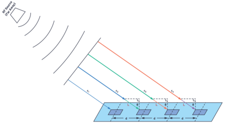
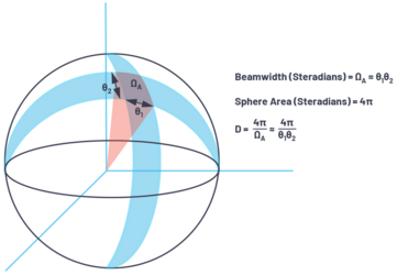
Transmitted RF signals are individually phase- and amplitude-shifted pre-coded before being fed into the individual elements of the array, allowing them to be routed in the desired direction. Under computer control, it is possible to change the beam direction, the beamwidth, the polarization, and the frequency of operation of the array.
An antenna array that uses beamforming ICs to drive high-gain beams over a range of angles. The antenna array is designed in such a way that the individual elements of patch antenna module are structurally combined into a main lobe that transmits energy in a given direction, while the overall system gain is determined by the number of elements in the array. For phased array antennas at VHF and UHF bands, SatixFy Prime DBF ASIC[126][127] can be used with an LNA (Low Noise Amplifier) and PA (Power Amplifer) without up- or down-converter.
In the Tx (transmission) mode, SDA with an active phased array, consisting of 48 patch antenna modules (each modules include 16 elements, 768 elements in total) in 3 segments of arrays (3 segments x 16 modules x 16 elements) with a coverage angle of 170° for each of elements, provides the synthesis of a directed radio wave with a power of up to 10W in the direction of end-point. The small deflection angle (less than 2°) of the direction of the radiation pattern and the dynamically controlled transmission power makes it possible to make the user hardly visible to electronic warfare equipment compared to antennas with a omnidirectional radiation pattern. The software method of synthesizing radio emission allows you to generate waves with a length of 500 ft (HF) to 5.9 in (L-band).
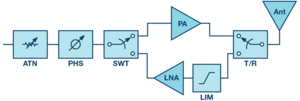
To start a radio session, such an antenna needs the geolocation of the end-point or relay ("handshake procedure"), to which the radio wave will be oriented. If we are talking about MUOS satellites, then information about their geostationary orbit is contained in the application data library. If we are talking about a radio exchange between two persons in LOS or BLOS mode, such information can be obtained through the IFF application.
In wide and narrow beam Rx mode, scans space according to the specified characteristics of RDF, PCSR, RWRC, RFDD applications.
Provides a stable connection with a remote person or several persons in LOS and BLOS conditions, incl. through terrestrial and satellite-based relays, with moving persons (user position, vehicles and aircraft). Tracks dynamically changing session characteristics and corrects the radiation pattern due to the phase shift.
| Frequency (f) | Wavelength (λ) | 1/2 Wavelength (λ/2) | 1/4 Wavelength (λ/4) | |||
| English | Metric | English | Metric | English | Metric | |
| 2 MHz | 491.8 ft | 149.9 m | 245.9 ft | 74.95 m | 123.0 ft | 37.48 m |
| 5 MHz | 196.7 ft | 59.95 m | 98.35 ft | 29.98 m | 49.18 ft | 14.99 m |
| 10 MHz | 98.36 ft | 29.98 m | 49.18 ft | 14.99 m | 24.59 ft | 7.495 m |
| 20 MHz | 49.18 ft | 14.99 m | 24.59 ft | 7.495 m | 12.295 ft | 3.748 m |
| 50 MHz | 19.67 ft | 5.995 m | 9.835 ft | 2.998 m | 4.9175 ft | 1.499 m |
| 100 MHz | 9.836 ft | 2.998 m | 4.918 ft | 1.499 m | 2.459 ft | 0.7495 m |
| 200 MHz | 4.918 ft | 1.499 m | 2.459 ft | 0.7495 m | 1.230 ft | 0.3748 m |
| 500 MHz | 1.967 ft | 0.5995 m | 0.9835 ft | 0.2998 m | 0.4918 ft | 0.1499 m |
| 1 GHz | 11.80 in | 29.97 cm | 5.9 in | 14.99 cm | 2.95 in | 7.493 cm |
| 2 GHz | 5.901 in | 14.99 cm | 2.951 in | 7.494 cm | 1.475 in | 3.747 cm |
| 5 GHz | 2.361 in | 5.997 cm | 1.181 in | 2.998 cm | 0.5903 in | 1.499 cm |
| 10 GHz | 1.180 in | 2.997 cm | 0.59 in | 1.499 cm | 0.295 in | 0.7493 cm |
| 20 GHz | 0.5901 in | 1.499 cm | 0.2951 in | 0.7494 cm | 0.1475 in | 0.3747 cm |
| 50 GHz | 0.2361 in | 0.5997 cm | 0.1181 in | 0.2998 cm | 0.05903 in | 0.1499 cm |
Advantages of SDA
- software-defined antenna consumes less power, yet has more power in each connection
- the software-defined antenna simultaneously provides the functions of communications, RF scanning, radio direction finding, drone and robot remote control, passive radar, radar warning receiver
- in the presence of radio interference (radio jamming[128]) by means of electronic warfare, a software-defined radio and an software-defined antenna are capable of using channels in a very wide range, including broadcasting bands (TV, FM), which have a large amplitude, and thus mask the radio transmission inside them[129]
- the antenna is compact and is mounted in the NVG mount and on the side of the helmet in the picatinny rails (3 segments)
- the feeder connecting the active part of the antenna with the electronic circuit of the radio is shorter
- no cables on the body to hook onto
Open source examples
Hardware
- software-defined (reconfigurable) antenna (installed in NVG mount and picatinny rails)
- built-in transmit-receive analog antennas in the ranges of the near radius of communications (Bluetooth, Wi-Fi, LTE, 5G)
- built-in analog radar warning system receiving antenna
- integrated analog antennas (manpack) for communications in VHF low, VHF high, UHF, UHF SAT, L/S bands
- integrated analog receiving antennas (manpack) for analysis and listening to the frequency ranges 2 MHz - 6.8 GHz
- integratable handheld portable short-range active metal re-radiation radar antenna
- close-range remote control of an active phased array radar (mobile or vehicle-mounted)
Specific cases for external integrated antennas
- A loop antenna with an in-phase whip antenna connected to it can provide an SDR receiver with a cardioid radiation pattern in order to use the DF signal function. Two users at a distance from each other with high accuracy determine the coordinates of the source of the local radio signal.
- Many-to-many communication relay from VHF/UHF band to HF and back can be provided by a ground support group consisting of tracked robots (one vertical pneumatic telescopic antenna and a dipole dual-band horizontal 10+10m antenna for 40/80m range), supported by two telescopic 9m pneumatic carbon suspensions, spread out to the sides by a servo and rack and pinion on the top of the vertical antenna, or two pneumatic carbon supports with pneumatic stops from below to adjust the angle of the supports and with braces from above to the end of the vertical mast of the vertical antenna. Automatic deployment and retraction of antennas. Perhaps 3 or 4 horizontal antennas on 3 or 4 supports.
- An option for quickly deploying a repeater and creating mesh networks can also be the use of 3 robotic dogs with pneumatic telescopic masts for antennas.
- Retransmission is also provided by a group of 3 or more aerostatically unloaded drones at an altitude of 900-3500m.
- Tracked robots also provide movement and rapid deployment of the radiation source for passive radars. The route of their movement and stop, as well as the ability to work on the move, should reduce the likelihood of destruction by enemy fire.
Interface examples
Insert picture for example
NET (Networks)
![]() →redirect Main Article: Networks
→redirect Main Article: Networks
Features
The app allows to configure networks, channels and routing for voice and data communications.
Channel priorities for different types of communications and data exchange can be set here: IMSG, CHAT, MAIL, SDR2, P2P. Includes settings for channel interchangeability in case of insufficient bandwidth of one of the networks. It evaluates the bandwidth of channels (available data transmission and reception rates) in real time.
User authorization in each network is based on time-limited tokens to the device.
The NET application is also an element of the hybrid mesh infrastructure of networks and serves mobile routing. For routing tasks, NET uses blockchain technology to verify the authenticity of the sender and his data, if they were transmitted through other users. Routing is done in the background and does not require user interaction. This feature extends and enhances the reliability of BLOS communications.
Routing:[130]
- Proactive routing, incl. Distance vector routing:
- This type of protocols maintains fresh lists of destinations and their routes by periodically distributing routing tables throughout the network.
- Distance-vector protocols are based on calculating the direction and distance to any link in a network.
- Each node maintains a vector (table) of minimum distance to every node. The cost of reaching a destination is calculated using various route metrics.
- Reactive routing:
- This type of protocol finds a route based on user and traffic demand by flooding the network with Route Request or Discovery packets.[131]
- Clustering can be used to limit flooding.
- The latency incurred during route discovery is not significant compared to periodic route update exchanges by all nodes in the network.
- Hybrid routing:
- The routing is initially established with some proactively prospected routes and then serves the demand from additionally activated nodes through reactive flooding.
- The choice of one or the other method requires predetermination for typical cases.
- Position-based routing
- Position-based routing methods use information on the exact locations of the nodes.
- This information is obtained for example via a GPS receiver. Based on the exact location the best path between source and destination nodes can be determined.
- Example: "Location-Aided Routing in mobile ad hoc networks" (LAR)
Interface examples
Insert picture for example
P2P (P2P & Cloud Computing)
![]() →redirect Main Article: P2P & Cloud Computing
→redirect Main Article: P2P & Cloud Computing
Features
Peer-to-peer networks are actively used in military and civilian data exchange, especially in the near radius, for example MANET[132][130]. Peer-to-peer (P2P) network - an overlay computer network based on the equality of participants. In such a network, there are no dedicated servers, and each node (peer) is both a client and performs the functions of a server. Unlike the client-server architecture, such an organization allows the network to remain operational with any number and any combination of available nodes. All nodes are members of the network.
There are a number of machines on the network, each of which can communicate with any of the others. Each of these machines can send requests to other machines to provide some resources within this network and thus act as a client. As a server, each machine must be able to process requests from other machines on the network, send out what was requested. Each machine must also perform some auxiliary and administrative functions (for example, keep a list of other known "neighbors" machines and keep it up to date).
Any member of this network does not guarantee its presence on a permanent basis. It can appear and disappear at any time. But when a certain critical network size is reached, there comes a moment when there are many servers with the same functions in the network at the same time.
The technology of peer-to-peer networks is also used for distributed computing. They allow in a relatively short time to perform a truly huge amount of calculations, which even on supercomputers would require, depending on the complexity of the task, many years and even centuries of work. This performance is achieved due to the fact that some global task is divided into a large number of blocks that are simultaneously executed by hundreds of thousands of computers participating in the project.
The peer-to-peer principle is applied in certain media streaming scenarios. Such technologies are most effective when a large number of clients are located within the same subnet or in interconnected subnets.
P2P network routing rules are configured in the NET application.
Benefits of P2P
- faster loading
- efficient use of resources
- access to a wide range of resources
- no single point of failure
Disadvantages of P2P
- P2P networks can also put a strain on network traffic
Connections
- one-to-many (distributed dynamic computing resources)
- many-to-one (user-specific resource allocation, remote access for multiple users, pooling requests)
- many-to-many (retransmission of radio signals, data exchange within the network)
Capabilities
- remote access of one or more users to real-time streaming data (user view exchange, RF scanning, radar data, user location for updating IFF)
- remote access to measurements of different users (weather data, ballistic calculations, measurement of characteristics of detected objects CVC, CAC, RDF)
- combining responses to IFF transponder requests from several users (reducing visibility due to fewer radio traffic sessions)
- collaboration in RDF application, CVC, CAC (triangulation method)
- joint dynamic CVC calculations, mainly for FR (Face recognition) preset
- relaying (mobile routing) of digital communication packages
- data exchange within the network
- sharing a single antenna for communications or RF scanning
Networks for P2P
| Network | Distance | Speed | Notice |
|---|---|---|---|
| Wi-Fi Direct, IEEE 802.11n (Wi-Fi 4) 2.4-2.5 / 5 GHz[133][134], P130-250mW | up to 90 m indoors
up to 500 m outdoors |
6.5-72.5 Mbps
up to 600 Mbps (4x4 MIMO) |
UPnP, DPWS |
| MANET (Mobile Ad-hock Network) (IEEE 802.11s) 2.4 / 5 GHz[135][132] | up to 90 m indoors
up to 500 m outdoors |
6.5-72.2 Mbps | HWMP |
| Wi-Fi IEEE 802.11ax (Wi-Fi 6/6E) 2.4 / 5 / 6 GHz | up to 120 m indoors
up to 700 m outdoors |
1.7-9.6 Gbps | |
| Bluetooth 5.2-5.3 (IEEE 802.15.1) 2.4 GHz, P2.5mW, RFI resistant, 128-bit AES encryption | up to 400 m | 2 Mbps | |
| WLAN 10,7-12,5 GHz Ku-band, 40ms latency | BLOS | 120 Mbps DL /
20 Mbps UL |
|
| LTE/5G FR1 410-7125 MHz and FR2 24-71 GHz | BLOS, mesh networks | 4.9 Gbps | |
| VHF / UHF / SHF | LOS, BLOS |
Interface examples
Insert picture for example
Here we briefly describe the functionality of the apps. You will find a more detailed description of the applications on their main articles pages. See the links below.
MAP (Maps)
![]() →redirect Main Article: Maps and Navigation
→redirect Main Article: Maps and Navigation
Features
The app based on the ATAK-Mil[136][137][138]SDK that has been deployed on over 250,000 devices in 15 DoD programs since 2010.
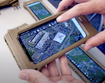
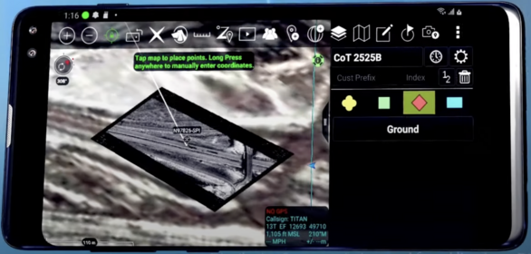
TAK capabilities:
- Complete Situational Awareness
Maps, GNSS positioning, users notices. TAK has the ability to display a wide variety of map data, either stored or downloaded in real-time. TAK is the USG's (Unattended Ground Sensors) premier tool for shared SA data and has the largest selection of features designed to facilitate real-time coordination between team members through the use of mission specific plugins.
- Pre-Mission Planning
Navigation tools, including viewshed analysis, help users select and traverse a pre-planned route buy displaying the elevation profile of the route along with speed, distance, and bearing to the next waypoint. Pre-mission planning is essential to enabling safe, effective, and rapid deployment of resources. TAK enables effective planning by providing a common understanding of exposure and vulnerabilities based on real time updates of any rapidly developing environment.
- Streamlined Deployment
Points, routes, drawing objects, and files can be shared through TAK user defined groups, teams or simply broadcasted. While most data sharing clients require a server, TAK’s CoT & chat sharing features can operate in a server-less environment amongst nodes operating on the same network. TAK Server can be introduced to extend client connectivity across networks or federated for persistent command and control.
- Streamlined Visibility
ATAK can display video either full screen or half screen, the latter giving access to the 3-D map at the same time. If the video source is a UAV, and the UAV is also publishing its own position and sensor point of interest (SPI), those can be plotted on the map. Being able to see the position of the aircraft and know where on the map the camera is looking in real time, while being able to see the video on the same screen, is a huge boost to SA.
- Improve Communication & Collaboration
The two most common communications methods are voice and text-based. While several plugins exists that provide VOIP within the application, ATAK does not have any built-in support for voice communications, mostly because the communications substrate and device (e.g., smartphone) usually has a native voice capability, whether it is a military radio or commercial cellular. ATAK does include a built-in chat application for text messages. Chat is a very common application, but most solutions require a server. Since ATAK was designed to be used in networks disconnected from any infrastructure, a server-less solution was needed. ATAK implemented a multicast-based chat service that requires no server. To support a wider variety of use-cases, we then extended it to be able to use point-to-point TCP in addition to the multicast-based chat. TAK plugins are maintained to allow in-app management of many standard issue military radios.
- Customize TAK for your needs
Military products available for license: ATAK-Mil, ATAK-Mil Plugins, ATAK-Mil SDK. The TAK core platforms support extensibility with a Software Development Kit (SDK), which enables any user group to develop mission-specific capability. ATAK is uniquely available as Government Open source Software (GOSS) from DoD's GitHub and vetted commercial developers are able to submit plugin source code to an automated build pipeline here at TAK.gov. This advancement allows the user community to leverage any valuable capability industry brings to the table, irrespective of the size of the company or their ability to secure a contract.
Open technology development reduces duplication, enables cost sharing, increases transparency, and encourages collaboration. The balance between autonomy and control is founded in TAK’s platform architecture, where the core components of the baselines are centrally managed, while plugins managed by a decentral, community driven methodology . Although plugin management is decentralized, partners should develop within the TAK Product Center government repositories for continuous integration, testing, validation, and accreditation.
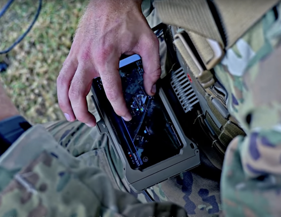
Currently, the TAK-Mil app is mainly used on mobile devices, forcing users to concentrate on the smartphone or tablet PC screen. This is less convenient than a Head-Up Display built into the field of view. No need to lose focus on environmental objects, no need to use your hands to control the interface.
Distinctive features of add-ons
- The TAK app will be deployed on a Linux-based OS and integrated into the ARHUDFM interface
- App control with HT (Hand tracking) and voice assistant (TESS) hands-free
- The application will include several add-ons that open in tabs of the same window or can be opened in different windows:
- Navigation (NAV)
- Path tracking (PATH)
- Mission planning (PLAN)
- Mission analysis (ANLS)
Interface examples
Insert picture for example
CMPS (Compass)
![]() →redirect Main Article: Maps and Navigation
→redirect Main Article: Maps and Navigation
Features
The Compass app allows you to continuously monitor azimuth and elevation. In integration with other applications (FA, CVC, CAC, IFF, RFDD, PCSR, EODD, APAR, RDF, RWRC, RPAC, RBRC, NAV) it is possible to see colored marks on the scale to turn the head exactly in the direction of the object of interest. The application opens in a separate LUW window.
The compass is required to accurately coordinate maneuver, position, and fire between Team Leader (TL), Rifleman (R), Grenadier rifleman (GR), Automatic rifleman (AR), and between firing groups within a squad.
Interface examples
Insert picture for example
![]() →redirect Main Article: Maps and Navigation
→redirect Main Article: Maps and Navigation
Features
The NAV application uses ATAK-MIL maps, GNSS positioning, and ground beacon positioning with the RDF application in case of GNSS signal distortion. The app opens in a separate window, has tabs: NAV, PATH, PLAN, ANLS.
NAV app native features:
- planning mission waypoints with statuses (separation, formation, evacuation, waiting)
- estimating the distance and time of route segments and the entire route
- evaluation of the experience of other users when using this route (incidents, warnings, reasons for deviation from the route, the state of the route, possible evacuation points)
- sending your own GNSS positions to another user and to the BMS (Battlefield Management System) analytics center
NAV capabilities in integration with other apps:
- integration with the IFF app allows to see the positions of "friend or foe" symbols on the map, which are displayed in the IFF navigation grid
- integration with the FA app allows to see the positions of captured targets on the map
- integration with the CVC and CAC apps allows to see the positions of detected objects on the map
- integration with the RDF app allows to see the positions of detected radio signal sources and positions of navigation beacons
- integration with RFDD, PCSR, RWRC, APAR apps allows to see the positions of detected objects on the map: aircraft, ground vehicles, radar and objects on the water surface
- integration with the RPAC application, RBRC allows to plan the waypoints of the drone and robot to launch an automatic mission, as well as see the routes of other friendly drones and robots on the map
- integration with the EODD application allows to see the marks of probable and definitely placed minefields
- formation of auto-tasks (waypoints) using the TSK app
Interface examples
Insert picture for example
PATH (Path tracking)
![]() →redirect Main Article: Maps and Navigation
→redirect Main Article: Maps and Navigation
Features
The app to track waypoints and automatically complete TSK auto-tasks (mission subtasks).
Native features of the PATH app:
- actual measurements of time and distance of route segments
- reporting events while following a route
- registration of deviations from the route and report on the reasons
- report on incidents, the state of the routes
Interface examples
Insert picture for example
GNSS (GNSS)
![]() →redirect Main Article: GNSS
→redirect Main Article: GNSS
Features
The app starts automatically and is available in LQM (Left quick menu) to open the GNSS application in a separate window.
The app allows to set up communication with geospatial positioning satellites (GPS, Galileo, QZSS), track positioning errors, notice the user.
In a situation of jamming GPS and other GNSS, triangulation by 4 or more navigation beacons, dropped or set in advance and whose coordinates are known (they wake up on schedule or on request). Or, the radio navigation function can be temporarily performed by individual users, in the IFF app, by emitting a periodic beacon signal at a predetermined frequency (for example, HF outside the voice range) along with the timecode of wave impulse leading edge, while being exactly on the place (at a safe distance from sources of threats), the geospatial positions of which are pre-marked on the map.
Interface examples
Insert picture for example
PLAN (Mission planning)
![]() →redirect Main Article: Maps and Navigation
→redirect Main Article: Maps and Navigation
Features
The app for mission planning, integrated with BMS and L-STE systems in use.
Capabilities:
- creating and editing a mission, defining mission objectives and required artifacts
- creation of mission routes in integration with the NAV app
- resource and reserve planning:
- time
- people
- vehicles
- ammunition
- medications
- food
- fuel
- batteries
- risk planning:
- loss of combat capability of people (taking into account the probability)
- loss of combat effectiveness, damage and malfunction of equipment
- risks of inaccurate planning of resources and reserves
- risks of inaccurate intelligence
- tactical schemes and priorities:
- movement tactics on various sections of the route
- schemes of communication in various sectors, channels, rules
- positions for observation and reconnaissance, assignment of roles
- spare positions
- possible evacuation points
- scheme of fire suppression of targets, fallback options
- withdrawal scheme due to unforeseen circumstances
- automatic creation of TSK tasks:
- formation of tasks with reference to geospatial position, number and characteristics of targets (surveillance, reconnaissance, destruction, deactivation, support, evacuation, logistics, etc.)
- group tasks, delegation rules
- individual tasks, delegation rules
- operational commands
Interface examples
Insert picture for example
ANLS (Mission analyzing)
![]() →redirect Main Article: Maps and Navigation
→redirect Main Article: Maps and Navigation
Features
The app is for mission performance analysis integrated with existing BMS and L-STE systems. The app analyzes deviations from the missions planned in the PLAN app and evaluates the effectiveness of individual and team decisions. The app evaluates the effectiveness of planning resources, reserves, risks, tactical schemes and priorities, as well as the compliance of the set and completed tasks (group and individual).
Interface examples
Insert picture for example
Brief of detection apps functionality
Here we briefly describe the functionality of the apps. You will find a more detailed description of the applications on their main articles pages. See the links below.
IFF (IFF control)
![]() →redirect Main Article: IFF Control, Transponder
→redirect Main Article: IFF Control, Transponder
Features
The IFF (Identification Friend-or-Foe)[139][140] application starts when you select the preset of the same name in the SB (Status bar) in the "Radio detection mode" section and opens the window of this application with a navigation grid.
IFF uses a transponder (transmitter-responder) of the Identificatiin Friend-or-foe system, which, in response to an encrypted interrogation signal received on one frequency, sends a short encrypted response message packet on another frequency containing an acknowledgment "Friend", Id, callsign and geospatial position. It is possible to use the blockchain architecture to increase the reliability of verification.
Depending on the selected preset in the SB (Status bar) in the "Stealth modes" section (STM app), the range of the IFF may be limited. The IFF will send a response message on different frequencies, on different networks and with different signal power (over a limited distance), or will not send a message. This is necessary for masking or radio silence.
Status Assignment
- Friend - correct transponder response received, status assigned automatically
- Assumed friend - expected positions of friendly forces in the PLAN app (mission planned) or NAV (actual position marks), no transponder response
- Civilian - identification by one of the users and registration manually using CVC detection systems or based on the received reliable visual confirmation (including on the basis of inspection); registration of the statuses entered by users is accompanied by an indication of their ID, date, time, position of the object detection, its destination course; or entered manually by the operator of the BMS (Battlefield Management System) analytical center based on satellite imagery, radio communications, and other types of identification
- Unknown - there is no or not enough data to assign a status
- Suspect - expected hostile positions or behavior characteristics of hostile forces
- Hostile - one of the users manually registered confirmations using visual surveillance or CVC, CAC (incl. GFL - Gunfire Locator), SDR2 + RDF, PCSR, RWRC, RFDD, APAR detection systems that allow to reliably identify an enemy object or combatant; registration of the statuses entered by users is accompanied by an indication of their ID, date, time, position of the object detection, its destination course; or entered manually by the operator of the BMS (Battlefield Management System) analytical center based on satellite imagery, radio communications, and other types of identification
- localized as the source of an oncoming shot (Gunfire Locator)
- localized as the source of an oncoming radar detector beam
- determined and localized visually, incl. according to BMS information located in enemy territory
- determined by passive radar locating
- determined by radio interception and RF source triangulation location direction finding
- communication session (voice, data, becon)
- remote control of a drone or robot
- no transponder response
Interrogation signals
Triggers:
- the IFF transponder with the specified interval at certain frequencies periodically generates and sends interrogation signals to an indefinite circle of people for registration and display on the navigation grid of one of the screens of user positions, with confirmation "Friend"
- when detected using CVC (1 user) and CAC (1 or more users, triangulation method), the IFF transponder sends a interrogation signal in the direction of the detected object with the statuses "Assumed friend", "Unknown", "Suspect"; depending on the protocol of actions, the status of these objects can be revised towards "Suspect"
- upon detection using SDR2 + RDF (2 or more users or 1 user with software-defined antenna, triangulation method), RFDD (1 user), PCSR (1 user), RWRC, APAR (1 user) radio signal sources (incl. reflected from the metal elements of the object) the IFF application compares their positions with the location of friendly forces on the navigation grid and the transponder sends an interrogation signal in the direction of the detected object with the statuses "Assumed friend", "Unknown", "Suspect"; depending on the protocol of actions, the status of these objects can be revised towards "Suspect"
- when launching a drone or robot that does not contain a transponder or perform a mission in autonomous mode, the IFF application using the NAV app checks their waypoints with the location of friendly forces on the navigation grid, if the positions of the object coincide with the planned route points, IFF automatically assigns the status of "Friend" to the object "
- when launching a drone or robot controlled manually through the RPAC and RBRC apps, the positions (including position history) of the drone or robot from these apps are transferred to the IFF app directly or through the NAV app, if the sequence of positions (position history) matches IFF automatically assigns the "Friend" status to the object
- when launching a drone or robot that does not have an IFF transponder and is manually controlled using another controller that is not integrated with the NAV app (integrated with ATAK-Mil database), the route data and characteristics of the drone or robot (model, MAC address, time and launch point) must be manually specified by its operator in the NAV app or in the ATAK-Mil system (if route information is available, but there is no transponder response, the "Asumed friend" status will be used; if there is no route information and the transponder response, the "Suspect" status will be used)
- request after radio direction finding (RDF) allows to pre-set the distance to the object and in the request message indicate the maximum range (radiation power) and directivity for response signal
Interrogation methods:
- interrogation signals are sent via an omnidirectional antenna (permissible if the risk of unmasking oneself is acceptable)
- interrogation signal are sent via an omnidirectional antenna in the short range "Stealth modes" - SD (Short distance visible only), e.g. via Bluetooth, Wi-Fi Direct (P2P) and UHF with limited transmission power over short distances
- interrogation signals are sent from a directional antenna (the omnidirectional pattern can be limited by a reflective grating or a software-defined antenna can be used) in the direction of the interrogated object (thus reducing the likelihood of unmasking due to a narrow beam of radio waves)
- interrogation signals are not sent in the "Stealth modes" - FULL (Zero emission) mode, but received updates in the IFF system performed by other users allow this user to have up-to-date awareness of the objects and their statuses on the IFF navigation grid
Response signals
- the transponder responds in "Stealth modes" OFF or IFF (IFF visible only) without restrictions; responses are provided only in motion with a displacement of more than 10-50 ft; in a stationary state, repeated requests are ignored, the previous position sent is assumed
- the transponder responds in "Stealth modes" SD (Short distance visible only) only for a limited distance
- in the P2P network settings, the function of combining responses to IFF transponder requests from several users can be enabled (reducing visibility due to fewer radio exchange sessions)
- the transponder does not respond in the "Stealth modes" - FULL (Zero emission) - in this case, for safety reasons, the mission and probable positions must be indicated in advance in the PLAN (ATAK-Mil data) app or actual positions that differ from the planned ones in the NAV app
- the transponder response message packet may include not only the position, but also vital signs data, ammunition stock, technical malfunctions of the device, if for some reason this information cannot be transmitted through other communication channels
Action protocols
- an area can be marked on the map, within which secret missions can be carried out, indicating the characteristics of objects, and therefore changing the status of unidentified objects with these characteristics towards "Suspect" is not allowed (only "Assumed friend" or "Unknown")
- operational intelligence data must be updated in a timely manner in the IFF system to identify objects with the status of "Hostile", so that the IFF system can unambiguously exclude them from their interrogation
Safety
IFF information is of high value to enemy forces, so encryption and data protection systems must have several levels of protection and control in real time.
Screen display
- 2 circle grid: land/sea and air, status symbols (Friend, Assumed friend, Civilian, Unknown, Suspect, Hostile)
- 2 circle grid with different scales (short-range and long-range)
- 1 half circle grid: land/sea or air, status symbols
- 1 circle gris and 1 half circle grid: Top view and Front/Left/Right view (cross/longitudinal section to display slope heights)
- window maximized 2x (display using Fading pads 50%-100% or Fading pads 25%-0%) the user has the ability to see through them and respond to movement!
- navigation grid dimension scaling (separately for each if more than one grid)
- display of object characteristics (object type, callsign, initials as in CHAT, Id) through the pointer inside the navigation grid or outside the navigation grid with highlighting this character on the grid
Network architecture
- for local data exchange, a P2P (peer-to-peer) network is initially provided
- VHF / UHF / UHF SAT / MUOS as additional networks for data exchange
- it is allowed to use an additional client-server architecture for integration with BMS (Battlefield Management System)
Hardware
VHF/UHF Transponder
Interface examples
The picture above shows an example of the user interface (click to open in a separate window, and then again to open in maximum quality and maximize):
- below left on the navigation grid you can see the localization of the source of enemy fire (GPS coordinates of the target are available to other users as well)
- the same navigation grid shows objects identified with the help of IFF (transponder), SDRS and RDF (radio interception and direction finding), PCSR (passive radar), CVC (Computer Vision), CAC (Computer Audition) - to make it easier to use the navigation grid there are layers and filters, as well as pop-up and audible tips
- navigation grid contains separately objects on the ground (on sea) and in the air, if you turn off the display of one of these 2 appearances, on this place there is additional reference information for the displayed appearance
- for each grid segment you can choose quick filters for what to display (6 Friend-or-Foe classes, weapon types or other filters)
- elements on the grid are active, the user, when selecting one or more elements, can see additional information about the object, can send data and its geolocation to the system or other users using the context menu, and can call a specific user or a group of users through one of the communication systems (instant messaging, text message with a voiceover, voice call, sending an image / video / data, streaming the view from his camera or another user / dog / robot / drone - 3-6-10 fps)
Facts. Statistics on IDF combat in urbanized areas show that every fifth fallen soldier (more than 21%) was killed by friendly fire (air raids, artillery fire, crossfire from light weapons).
In the Russian-Ukrainian war, up to 40 percent were non-combat losses. The reasons are defeat by friendly fire due to lack of interaction with neighbors, transport accidents, and illness. Almost 1 in 4 of American soldiers killed during Desert Storm, died by friendly fire. Three quarters of all American Abrams tanks and Bradley Fighting Vehicles destroyed or damaged in the war were taken down by friendly fire.[141]
Friendly fire casualties (fatal and non-fatal) estimates since WW2:[142]
| Campaign | Percent Casualties (U.S. Military only)* |
|---|---|
| World War II | 21% |
| Korea | 18% |
| Vietnam | 39% |
| Persian Gulf | 52% |
| Panama | .08% |
| Haiti | 0% |
| Iraq | 41% |
| Afghanistan | 13% |
SDRS (SDR Scan)
![]() →redirect Main Article: SDR Scan, Software Defined Radio
→redirect Main Article: SDR Scan, Software Defined Radio
Features
The SDRS (SDR Scan - Software Defined Radio Scanning ) app opens in a separate window and is designed to scan, decode, analyze, listen (analog and unencrypted signals), relay radio frequencies in the 1 MHz - 6 GHz range, including TV and radio broadcasting bands, amateur / trunking radio bands, radar, air navigation, radio beacons, mobile communication frequencies (3G / 4G / 5G), wireless networks, including signals with multiple RF carriers - combined signals into one signal (multiplexing[129], for example, OFDM). Uses CVC (Computer Vision Control) and AI filters and algorithms to automatically recognize the graphic shape of 2D / 3D spectrum, waterfall patterns for signals.
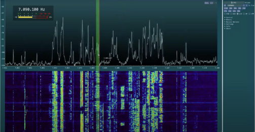
Radio signal analysis and measurement parameters include frequency, bandwidth, modulation, polarization, waveforms, likely encryption model.
Analysis can be performed manually and automatically according to pre-configured automation functions (ML algorhitms). The user has access to brief and detailed reports of the app, as well as recommendations.
In integration with the RDF app, the user can immediately, together with another user or independently (using a software-based antenna), determine the direction and position of the radio signal source (triangulation method).
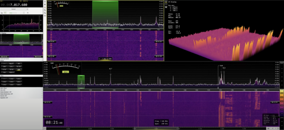
Advantages
When using the automatic modes of the app, 1-2 days of user training is enough for effective regular use.
Up to 12 parallel scan threads.
At the same time, each user becomes part of the SIGINT system, so situational awareness of enemy movements and positions becomes clear and detailed at any time of the day, in any weather.
In today's active environment, every movement and tactical task is accompanied by the reception and transmission of radio signals. Even if radio silence is temporarily applied, drones are used to assess situational awareness. A unit cannot remain without communication for long periods of time.
Open source examples
Hardware
SDR IC, 12-bit 8-ch ADC and DAC based
Interface examples
Insert picture for example
RDF (Radio direction finding control)
![]() →redirect Main Article: Radio Direction Finding Control
→redirect Main Article: Radio Direction Finding Control
Features
The RDF (Radio direction finding[143] control) app is designed to determine the direction and distance to the radio signal source by triangulation method. The app can open in a separate window or run in the background. Typically used in integration with SDRS, IFF, SDR2 application.
When using an analog antenna, the multi-user mode is configured through the peer-to-peer network in the P2P app. When using a software-defined antenna (SDA), measurements can be made by a single user.
Details
- the RDF app applies the radio direction finding of received radio frequencies identified as potentially unknown or threatening (radar, EW&SIGINT[144], ECM[145][146]) or identified as a source of RF carrier (analogue or digital signal) for communication
- the RDF app calculates the position of the detected source and sends a packet to update the IFF system - the detected object, after requesting user confirmation, is transferred to the rescanning mode at regular intervals (thus, the direction of movement and the average speed of the object can also be displayed on the IFF navigation grid)
- in accordance with the current rules and restrictions, the mission can initiate the task of interrogating the detected object for the above IFF app if there are no confirmations of the status of the object
- in the conditions of distortion or suppression of radio signals of GNSS navigation satellite systems, the RDF app is used for radio navigation and positioning using terrestrial radio beacons operating in other frequency bands, including FM, TV broadcasting and mobile comms bands
Interface examples
Insert picture for example
PCSR (Passive covert surveillance radar)
![]() →redirect Main Article: Passive Covert Radar Control, Passive Radar
→redirect Main Article: Passive Covert Radar Control, Passive Radar
Features

Passive covert surveillance radar (PCSR) app for an external device - SDA (Software Defined Antenna), which is installed on the device from above in the NMG mount, picatinny rails and connected to the USB/Thenderbolt connector.
The app for a type of passive[147] (bistatic[148] or multistatic[149]) non-native radiation radar, that detects and tracks every 0.5-1 s objects by processing reflections from non-cooperating ambient RF lighting sources such as commercial broadcast and communications signals, as well as echoes from other radars whose positions are known. They allow to calculate the location, direction and speed of an object. In some cases it is possible to use signals from multiple transmitters to make multiple independent measurements of bistatic range, Doppler shift, and direction finding, and therefore greatly improve the accuracy of the final path.
Irradiator Sources
- enemy and friendly radars:
- D-band ƒ 1-2 GHz λ 30-15 cm
- E- and F-band ƒ 2-4 GHz λ 150-75 mm
- G- and H-band 4-8 GHz λ 75-37 mm
- I- and J-band 8-18 GHz λ 37-17 mm
- UHF TV: ƒ 470-806 MHz λ 64-37 cm
- VHF high TV: ƒ 174-216 MHz λ 172-139 cm
- FM radio: ƒ 88-108 MHz (76-90 MHz in Japan) λ 340-278 cm
- VHF low TV: ƒ 54-88 MHz λ 555-340 cmOf primary interest for the development of PCSR (Passive covert surveillance radar) technology is UHF TV (470-806 MHz), D-band (1-2 GHz), E/F-band (2-4 GHz), and G/H-band (4-8 GHz), where many military mobile radars (battlefield surveillance, weapons control and ground reconnaissance) with short and medium ranges traditionally operate. As passive radar technology evolves, using illumination on broadcast radio frequencies[150] and friendly or enemy radar illumination for frequencies in the NATO D-, E-, F-band (1-4 GHz), the existing technology will not require significant changes because it is initially based on the ultrawideband 2MHz - 8GHz (Ultrawideband, UWB).
The use of the 8-40 GHz NATO I-, J-, K-band requires an upgrade or optional helmet-mounted modules to be connected to the device. The 25-60 GHz range of miniaturized sensors is developing very rapidly as these technologies are actively used in the automotive industry. We can envision various infantry, artillery, and light armored units using a low power pulsed irradiator mounted on a robot or drone that provides human-safe illumination in this range at a range of less than one nautical mile for all friendly forces operating in the area. This will allow us to have dozens or hundreds of mobile personal antennas in different localizations and recognize numerous metallic / water and animal objects, even small ones, and then use machine learning patterns to identify what is detected. This will include identifying friendly forces (on the IFF navigation grid) that are in radio silence (snipers, spotters, cavalry scouts, recon and cover forces).
-
Radar Sensors 12-60GHz
-
Radar Sensors 25-60GHz
-
Radar Sensors 25-60GHz
-
Radar Sensors 25-60GHz
How it works

Built-in SDRS function will scan and analyze RF bands in the range of 2 MHz to 8 GHz and thus detect the threat of radar exposure and to find fited RF carrier. A software-defined antenna (SDA) capable of interrogating the RF spectrum in the form of several beams simultaneously with a narrow radiation pattern in the form of a dome with high frequency and receiving radio wave at several reception points, fixing the detection angle (phase offsets). After that the triangulation calculation (RDF) allows to localize the location and direction angle of irradiator source.
Now in its own coordinate system the passive radar can use selected RF carriers to search for reflected signals received from other directions. Several points of reflection from object (metall, water / human) already allow to estimate its silhouette, and Doppler radar measure allows to estimate speed and direction of motion.
Radar Cross Section
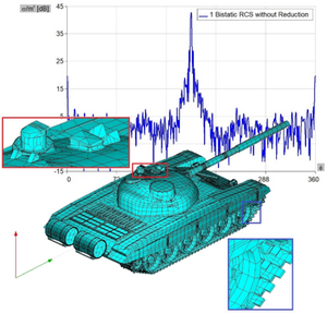
Radar cross-section (RCS), denoted σ, also called radar signature, is a measure of how detectable an object is by radar. A larger RCS indicates that an object is more easily detected.[151][152]
An object reflects a limited amount of radar energy back to the source. The factors that influence this include:
- the material with which the target is made;
- the size of the target relative to the wavelength of the illuminating radar signal;
- the absolute size of the target;
- the incident angle (angle at which the radar beam hits a particular portion of the target, which depends upon the shape of the target and its orientation to the radar source);
- the reflected angle (angle at which the reflected beam leaves the part of the target hit; it depends upon incident angle);
- the polarization of the radiation transmitted and received with respect to the orientation of the target.
While important in detecting targets, strength of emitter and distance are not factors that affect the calculation of an RCS because RCS is a property of the target's reflectivity.
More precisely, the RCS of a radar target is the hypothetical area required to intercept the transmitted power density at the target such that if the total intercepted power were re-radiated isotropically, the power density actually observed at the receiver is produced.[153] This statement can be understood by examining the monostatic (radar transmitter and receiver co-located) radar equation one term at a time:
where
- = transmitter's input power (watts)
- = gain of the radar transmit antenna (dimensionless)
- = distance from the radar to the target (meters)
- = radar cross-section of the target (meters squared)
- = effective area of the radar receiving antenna (meters squared)
- = power received back from the target by the radar (watts)
The term in the radar equation represents the power density (watts per meter squared) that the radar transmitter produces at the target. This power density is intercepted by the target with radar cross-section , which has units of area (meters squared). Thus, the product has the dimensions of power (watts), and represents a hypothetical total power intercepted by the radar target. The second term represents isotropic spreading of this intercepted power from the target back to the radar receiver. Thus, the product represents the reflected power density at the radar receiver (again watts per meter squared). The receiver antenna then collects this power density with effective area , yielding the power received by the radar (watts) as given by the radar equation above.
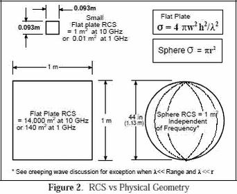 |
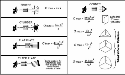 |
Figures 2 and 3 show[154] that RCS does not equal geometric area. For a sphere, the RCS, F = Br2, where r is the radius of the sphere.
The RCS of a sphere is independent of frequency if operating at sufficiently high frequencies where λ<<Range, and λ<< radius (r). Experimentally, radar return reflected from a target is compared to the radar return reflected from a sphere which has a frontal or projected area of one square meter (i.e. diameter of about 44 in). Using the spherical shape aids in field or laboratory measurements since orientation or positioning of the sphere will not affect radar reflection intensity measurements as a flat plate would. If calibrated, other sources (cylinder, flat plate, or corner reflector, etc.) could be used for comparative measurements.
To reduce drag during tests, towed spheres of 6", 14" or 22" diameter may be used instead of the larger 44" sphere, and the reference size is 0.018, 0.099 or 0.245 m2 respectively instead of 1 m2. When smaller sized spheres are used for tests you may be operating at or near where λ-radius. If the results are then scaled to a 1 m2 reference, there may be some perturbations due to creeping waves. See the discussion at the end of this section for further details.
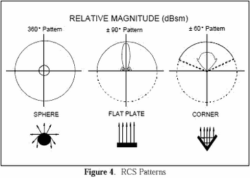
|
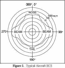
|
In Figure 4, RCS patterns are shown as objects are rotated about their vertical axes (the arrows indicate the direction of the radar reflections).
The sphere is essentially the same in all directions. The flat plate has almost no RCS except when aligned directly toward the radar. The corner reflector has an RCS almost as high as the flat plate but over a wider angle, i.e., over ±60°. The return from a corner reflector is analogous to that of a flat plate always being perpendicular to your collocated transmitter and receiver. Targets such as ships and aircraft often have many effective corners. Corners are sometimes used as calibration targets or as decoys, i.e. corner reflectors.
An aircraft target is very complex. It has a great many reflecting elements and shapes. The RCS of real aircraft must be measured. It varies significantly depending upon the direction of the illuminating radar.
Figure 5 shows a typical RCS plot of a jet aircraft. The plot is an azimuth cut made at zero degrees elevation (on the aircraft horizon). Within the normal radar range of 3-18 GHz, the radar return of an aircraft in a given direction will vary by a few dB as frequency and polarization vary (the RCS may change by a factor of 2-5). It does not vary as much as the flat plate.
As shown in Figure 5, the RCS is highest at the aircraft beam due to the large physical area observed by the radar and perpendicular aspect (increasing reflectivity). The next highest RCS area is the nose/tail area, largely because of reflections off the engines or propellers. Most self-protection jammers cover a field of view of +/- 60 degrees about the aircraft nose and tail, thus the high RCS on the beam does not have coverage. Beam coverage is frequently not provided due to inadequate power available to cover all aircraft quadrants, and the side of an aircraft is theoretically exposed to a threat 30% of the time over the average of all scenarios.
Typical radar cross sections are as follows: Missile 0.5 sq m; Tactical Jet 5 to 100 sq m; Bomber 10 to 1000 sq m; and ships 3,000 to 1,000,000 sq m. RCS can also be expressed in decibels referenced to a square meter (dBsm) which equals 10 log (RCS in m2). RCS (dBsm) = 10.0 * log10 (linear RCS).
Again, Figure 5 shows that these values can vary dramatically. The strongest return depicted in the example is 100 m2 in the beam, and the weakest is slightly more than 1 m2 in the 135°/225° positions. These RCS values can be very misleading because other factors may affect the results. For example, phase differences, polarization, surface imperfections, and material type all greatly affect the results. In the above typical bomber example, the measured RCS may be much greater than 1000 square meters in certain circumstances (90°, 270°).
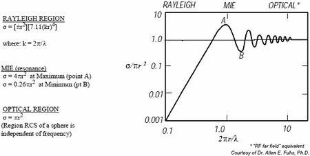 |
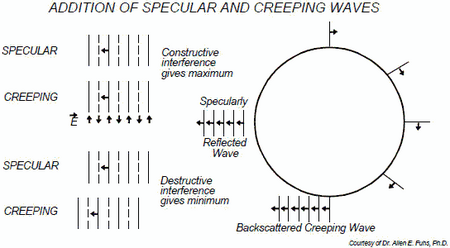 |
The initial RCS assumptions presume that we are operating in the optical region (λ<<Range and λ<<radius). There is a region where specular reflected (mirrored) waves combine with back scattered creeping waves both constructively and destructively as shown in Figure 7. Creeping waves are tangential to a smooth surface and follow the "shadow" region of the body. They occur when the circumference of the sphere - λ and typically add about 1 m2 to the RCS at certain frequencies. Factors
- Size. As a rule, the larger an object, the stronger its radar reflection and thus the greater its RCS. Also, radar of one band may not even detect certain size objects. For example, 10 cm (E/F-band radar, 2-4 GHz) can detect rain drops but not clouds whose droplets are too small
- Materials such as metal are strongly radar reflective and tend to produce strong signals. Wood and cloth or plastic and fibreglass are less reflective or indeed transparent to radar making them suitable for radomes. Even a very thin layer of metal can make an object strongly radar reflective.
- Radar absorbent paint. The SR-71 Blackbird and other aircraft were painted with a special "iron ball paint" that consisted of small metallic-coated balls. Radar energy received is converted to heat rather than being reflected.
- Shape, directivity and orientation. The surfaces of the F-117A are designed to be flat and very angled. This has the effect that radar will be incident at a large angle (to the normal ray) that will then bounce off at a similarly high reflected angle; it is forward-scattered. The edges are sharp to prevent rounded surfaces which are normal at some point to the radar source. As any ray incident along the normal will reflect back along the normal, rounded surfaces make for a strong reflected signal. From the side, a fighter aircraft will present a much larger area than the same aircraft viewed from the front. All other factors being equal, the aircraft will have a stronger signal from the side than from the front; hence the orientation of the target relative to the radar station is important.
- Smooth surfaces. The relief of a surface could contain indentations that act as corner reflectors which would increase RCS from many orientations. This could arise from open bomb-bays, engine intakes, ordnance pylons, joints between constructed sections, etc. Also, it can be impractical to coat these surfaces with radar-absorbent materials.
Measurement
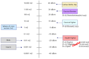
Typical values for a centimeter wave radar (E/F/G/H-band ƒ 2-8 GHz λ 150-37 mm) are:
- Insect: 0.00001 m2
- Bird: 0.01 m2
- Stealth aircraft: <0.1 m2 (e.g. F-117A .003 m2, F-22 Raptor .0065 m2, B-2 Spirit .0014 m2)
- Surface-to-air-missile: ≈0.1 m2
- Human: 1 m2
- Human with rifle: 1-4 m2[155][156][157]
- Small combat aircraft: 2–3 m2 (F-18 1 m2)
- Large combat aircraft: 5–6 m2
- Civilian car: 8-21 m2
- Armored vehicle: 12-80 m2
- Tank: 20-200 m2
- Cargo aircraft: up to 100 m2
- Coastal trading vessel (55 m length): 300–4000 m2
- Corner reflector with 1.5 m edge length: ≈20,000 m2
- Frigate (103 m length): 5000–100,000 m2
- Container ship (212 m length): 10,000–80,000 m2

This is where the properties of multistatic radar come in handy, because different sources with different wavelengths can be used alternately, and the receivers of multiple users are at different angles to the surface of the object. It is conceivable that some users will detect a very faint and indistinct reflected signal while other users will be able to receive a more prominent signal. In the end, the information will be recorded in a single information system in any case.
Capabilitites
- in integration with the ANTC - SDA app allows to use up to 24 beams of radio waves with different beam angles (deflection angle 16-2°), for primary detection, clarification and for amplifying the received radar signal
- in integration with the SDRS app allows to identify radar signals by the type of radio signal sources
- in integration with the RDF app allows to dynamically calculate the distance, azimuth, elevation, speed and destination course of the detected radars
- in integration with the IFF app allows to display on the navigation grid in different viewpoints of the radar on the plan, frontal and side sections
- in integration with the CMPS app, it helps to focus the line of sight on the detected radar (if it is in the field of view)
- can be used as an addition to the mobile remote controlled radar (APAR)
- allows to detect even small metal objects in the air (with and without radar turned on), on the surface of the earth and water at a distance of up to 3 miles
- passive means that it does not emit radiation during operation
Advantages
- Lower price
- Minimal energy consumption
- No maintenance, due to the lack of transmitter and moving parts
- Covert operation, including no need for frequency allocations
- Physically small and hence easily deployed in places where conventional radars cannot be
- Rapid updates, typically once a second
- Difficulty of jamming
- Resilience to anti-radiation missiles
Disadvantages
- Reliance on third-party illuminators
- 1D/2D operation, but possible use 2 different systems for 3D (height + range)
Interface examples
The picture above shows an example of the user interface (click to open in a separate window, and then again to open in maximum quality and maximize):
- a red dot is visible on the compass field on the left side, indicating the azimuth of the destination to radar location (112°) and elevation (5°)
- below right, a large "Warning! Radar Detection" icon is displayed that tells you the direction of the oncoming radar irradiation (2h), range to source (4743yd), elevation (5°)
- below left on the navigation grid you can see the localization of the source of enemy radars (GPS coordinates of the target are available to other users as well)
- the same navigation grid shows objects identified with the help of IFF (transponder), SDRS and RDF (radio interception and direction finding), PCSR (passive radar), CVC (Computer Vision) and CAC (Computer Audition), incl. GFL (Gunfire Locator) - to make it easier to use the navigation grid there are layers and filters, as well as pop-up and audible tips
- in the window in the center, this target is not displayed in the priority list for this user because there are users who are closer to the target and for them it will be a higher priority - AI evaluates the probability of crossfire and optimizes targets
Disruptive capabilities.
Just imagine the practical capabilities of passive radar technology if all soldiers in contact with the enemy were equipped with it. From then on, snipers will be visible in advance of their first shot, several miles away, in any weather and time of day, even if they are inside a reinforced concrete building, much less in open terrain where any people can be detected and civilians and combatants, immobile, wounded, can be recognized. Reconnaissance teams and saboteurs, ambushes, patrols, UAVs without radio communications under AI control, fire spotters, ballistic and guided ammunition, friendly forces in radio silence. Simultaneously casualty evacuation, search and rescue, dead evacuation.
The value of the technology cannot be overestimated. But it can be multiplied if Gunfire Locator (GFL) and CAC, IFF, CVC, counter drone RFDD, counter mine EODD, drone control RPAC, RBRC, SDRS, RDF, BMS technologies are used together with it. Reconnaissance capabilities and enemy contact range will multiply. And with them, lethality and mission effectiveness will increase significantly.
Finally, passive radar technology is one way to determine geospatial location when GNSS (incl. GPS) signals are distorted or jammed.
RWRC (Radar warning receiver control)
![]() →redirect Main Article: Radar Warning Receiver Control
→redirect Main Article: Radar Warning Receiver Control
Features
The RWRC (Radar warning receiver[158] control) app allows to use the mode of detecting exposure from air defense radars and counter-battery radars[159], displays on the screen in a window with an IFF navigation grid and / or a NAV map the location of these radars. It is indispensable when performing tactical tasks of mortar and artillery fire in order to have time to change position in case of detection.

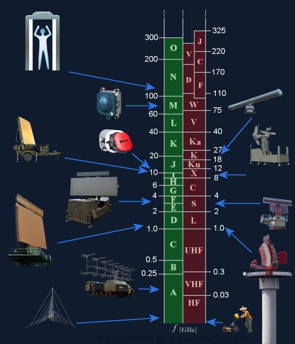
Radar Bands
HF (3-30 MHz) and VHF (30-300 MHz) band / NATO RF A-band
These radar bands 3-30 MHz (λ 100-10 m) and 30-300 MHz (λ 10-1 m) have a long tradition, as the first radar sets were developed here before and during the 2nd World War. The frequency range corresponded to the high-frequency technologies mastered at that time. Later, they were used for early warning radars of extremely long-range, so-called Over The Horizont (OTH) radars. Since the accuracy of angle determination and the angular resolution depends on the ratio of wavelength to antenna size, these radars cannot meet high accuracy requirements. The antennas of these radar sets are nevertheless extremely large and can even be several kilometers long. Here special abnormal propagation conditions act, which increase the range of the radar again at the expense of the accuracy. Since these frequency bands are densely occupied by communication radio services, the bandwidth of these radar sets is relatively small.
VHF low TV: ƒ 54-88 MHz λ 555-340 cm
FM radio: ƒ 88-108 MHz (76-90 MHz in Japan) λ 340-278 cm
VHF high TV: ƒ 174-216 MHz λ 172-139 cm
UHF TV: ƒ 470-806 MHz λ 64-37 cm
These frequency bands are currently experiencing a comeback, while the actually used Stealth technologies don't have the desired effect at extremely low frequencies.
UHF band (300-1000 MHz) / NATO RF B- and C-band
For this frequency band UHF 300-1000 MHz (λ 100-30 cm), specialized radar sets have been developed which are used as military early warning radar, for example for the Medium Extended Air Defense System (MEADS), or as wind profilers in weather observation. These frequencies are damped only very slightly by weather phenomena and thus allow a long-range.
Newer methods, so-called ultrawideband (Ultrawideband, UWB) radars, transmit with very low pulse power from the A to the C band (HF, VHF, UHF) and are mostly used for technical material investigation or partly in archaeology as Ground Penetrating Radar (GPR).

L band (1-2 GHz) / NATO RF D-band
This range 1-2 GHz, λ 30-15 cm is ideally suited for modern long-range air surveillance radars up to a range of 250 nautical miles (≈400 km). Relatively low interference from civil radio communication services enables broadband radiation with very high power. They transmit pulses with high power, wide bandwidth and an intrapulse modulation to achieve even longer ranges. Due to the curvature of the earth, however, the range that can be practically achieved with these radar sets is much smaller at low altitudes, since these targets are then obscured by the radar horizon.
In this frequency band the En-Route Radars or Air Route Surveillance Radars (ARSR) work for air traffic control. In conjunction with a Monopulse Secondary Surveillance Radar (MSSR), these radars operate with a relatively large, slowly rotating antenna. (L-band: like large antenna and long-range). The designator L-Band is good as mnemonic rhyme as large antenna or long range.
S band (2-4 GHz) / NATO RF E- and F-band
In the frequency band from 2 to 4 GHz, λ 150-75 mm the atmospheric attenuation is higher than in the D-band. Radar sets require a much higher pulse power to achieve long-ranges. An example is the older one military Medium Power Radar (MPR) with up to 20 MW pulse power. In this frequency band, considerable impairments due to weather phenomena are already beginning to occur. Therefore a couple of weather radars work in E/F-Band but more in subtropic and tropic climatic conditions, because here the radar can see beyond a severe storm.
Special Airport Surveillance Radars (ASR) are used at airports to detect and display the position of aircraft in the terminal area with a medium range up to 50 … 60 NM (≈100 km). An ASR detects aircraft position and weather conditions in the vicinity of civilian and military airfields. The designator S-Band is good as mnemonic rhyme as smaller antenna or shorter range (contrary to L-Band).
AN/TPS-80 Ground/Air Task Oriented Radar (2-4 GHz):[161]

C band (4-8 GHz) / NATO RF G- and H-band
For this frequency band from 4 to 8 GHz, λ 75-37 mm mobile military battlefield radars with short and medium range are used. The antennas are small enough to be quickly installed with high precision for weapon control. The influence of weather phenomena is very large, which is why military radar sets are usually equipped with antennas with circular polarization. In this frequency range, most weather radars are also used for moderate climates.
X (8-12 GHz) and Ku (12-18 GHz) / NATO RF I- and J-band
Between 8 and 12 GHz, λ 37-25 mm and 12-18 GHz, λ 25-17 mm, the ratio of wavelength to antenna size has a more favorable value. With relatively small antennas, sufficient angular accuracy can be achieved, which favours military use as airborne radar. On the other hand, the antennas of missile control radar systems, which are very large relative to the wavelength, are still handy enough to be considered as deployable.
This frequency band is mainly used in civil and military applications for maritime navigation radar systems. Small cheap and fast rotating antennas offer sufficient ranges with very good precision. The antennas can be constructed as simple slot radiators or patch antennas.
This frequency band is also popular for space borne or airborne imaging radars based on Synthetic Aperture Radar (SAR) both for military electronic intelligence and civil geographic mapping. A special application of the Inverse Synthetic Aperture Radar (ISAR) is the monitoring of the oceans to prevent environmental pollution.
K (18-27 GHz) and Ka (27-40 GHz) / NATO RF K-band
As the emitted frequency increases from 18 to 27 GHz, λ 17-11 mm and 27-40 GHz, λ 11-7.5 mm, the attenuation in the atmosphere increases but the possible accuracy and range resolution increases too. Large ranges can no longer be achieved. Radar applications in this frequency range are, for example, airfield surveillance radar, also known as Surface Movement Radar (SMR) or (as part of) Airport Surface Detection Equipment (ASDE). With extremely short pulses of a few nanoseconds, an excellent range resolution is achieved so that the contours of aircraft and vehicles can be seen on the display.
V (40-75 GHz) / NATO RF L-band
Due to molecular scattering of the atmosphere the electromagnetic waves suffer a very strong attenuation. Radar applications are limited to a range of a few ten meters.
W (75-110 GHz) / NATO RF M-band
Two phenomena of atmospheric attenuation can be observed here. A maximum of attenuation at about 75 GHz and a relative minimum at about 96 GHz. Both frequencies are used practically. At about 75 to 76 GHz, short-range radar sets are used in automotive engineering as parking aids, brake assist systems and automatic accident avoidance. This high attenuation through molecular scattering (here through the oxygen molecule O2) prevents mutual interference through mass use of these radar sets.
There are radar sets operating at 96 to 98 GHz as laboratory equipments yet. These applications give a preview for a use of radar in extremely higher frequencies as 100 GHz.
D (110-170 GHz) and Y (170-260 GHz) / NATO RF N- and O-band
In the 122 GHz range there is another ISM band for measurement applications. Since in high-frequency technology the Terahertz range is defined from 100 GHz = 0,1 THz to 300 GHz, the industry offers radar modules for this frequency range as “Terahertz radar”. These Terahertz radar modules are used, for example, in so-called full-body scanners. Full-body scanners take advantage of the fact that although these Terahertz frequencies can easily penetrate dry and non-conductive substances, they cannot penetrate the skin deeper than just a few millimeters due to the moisture of the human skin.
Conclusion
Of primary interest for the development of RWRC (Radar warning receiver control) technology is the C-band (NATO G/H-band, 4-8 GHz), where many military mobile radars (battlefield surveillance, weapons control and ground reconnaissance) with short and medium ranges traditionally operate. As passive radar technology evolves, using illumination on broadcast radio frequencies[150] and friendly or enemy radar illumination for frequencies in the NATO D-, E-, F-band (1-4 GHz), the existing technology will not require significant changes because it is initially based on the ultrawideband 2MHz - 8GHz (Ultrawideband, UWB).
The use of the 8-40 GHz NATO I-, J-, K-band requires an upgrade or optional helmet-mounted modules to be connected to the device. The 25-60 GHz range of miniaturized sensors is developing very rapidly as these technologies are actively used in the automotive industry. We can envision various infantry, artillery, and light armored units using a low power pulsed irradiator mounted on a robot or drone that provides human-safe illumination in this range at a range of less than one nautical mile for all friendly forces operating in the area. This will allow us to have dozens or hundreds of mobile personal antennas in different localizations and recognize numerous metallic / water and animal objects, even small ones, and then use machine learning patterns to identify what is detected. This will include identifying friendly forces (on the IFF navigation grid) that are in radio silence (snipers, spotters, cavalry scouts, recon and cover forces).
-
Radar Sensors 12-60GHz
-
Radar Sensors 25-60GHz
-
Radar Sensors 25-60GHz
-
Radar Sensors 25-60GHz
How it works
Built-in SDRS function will scan and analyze RF bands in the range of 2 MHz to 8 GHz and thus detect the threat of radar exposure. A software-defined antenna (SDA) capable of interrogating the RF spectrum in the form of several beams simultaneously with a narrow radiation pattern in the form of a dome with high frequency and receiving radio wave at several reception points, fixing the detection angle (phase offsets). After that the triangulation calculation allows to localize the location of a metallic object that reflected the received wave. Several points of reflection from this object already allow to estimate its silhouette, and Doppler radar measure allows to estimate speed and direction of motion.
Capabilities
- in integration with a passive analog omnidirectional antenna tuned to the frequency bands of the radar allows you to detect the impulse signal of the radar
- integrated with the IMSG and TSK app for fast response to threats
- in integration with the ANTC - SDA app allows to use up to 24 beams of radio waves with different beam angles (deflection angle 16-2°), for primary detection, clarification and for amplifying the received radar signal
- in integration with the SDRS app allows to identify radar signals by the type of radio signal sources
- in integration with the RDF app allows to dynamically calculate the distance, azimuth, elevation, speed and destination course of the detected radars
- in integration with the IFF app allows to display on the navigation grid in different viewpoints of the radar on the plan, frontal and side sections
- in integration with the CMPS app, it helps to focus the line of sight on the detected radar (if it is in the field of view)
- can be used as a complement to passive radar (PCSR) when enemy radars are used as an irradiator
- does not emit radiation during operation
Interface examples
The picture above shows an example of the user interface (click to open in a separate window, and then again to open in maximum quality and maximize):
- a red dot is visible on the compass field on the left side, indicating the azimuth of the destination to radar location (112°) and elevation (5°)
- below right, a large "Warning! Radar Detection" icon is displayed that tells you the direction of the oncoming radar irradiation (2h), range to source (4743yd), elevation (5°)
- below left on the navigation grid you can see the localization of the source of enemy radars (GPS coordinates of the target are available to other users as well)
- the same navigation grid shows objects identified with the help of IFF (transponder), SDRS and RDF (radio interception and direction finding), PCSR (passive radar), CVC (Computer Vision) and CAC (Computer Audition), incl. GFL (Gunfire Locator) - to make it easier to use the navigation grid there are layers and filters, as well as pop-up and audible tips
- in the window in the center, this target is not displayed in the priority list for this user because there are users who are closer to the target and for them it will be a higher priority - AI evaluates the probability of crossfire and optimizes targets
APAR (Active phased array radar control)
![]() →redirect Main Article: APAR RC
→redirect Main Article: APAR RC
Features
Active phased array radar[162][163] remote control (APAR) is an application for remote control at a safe distance of a low-observable mobile active (radiating) radar with an active phased array and data exchange with it.
Solid-state radar transceiver modules are directed in different directions without moving the antenna.
Capabilities
- integrated with IFF app to display detected objects on a navigation gris inside a multi-user P2P (peer-to-peer) network
- can be used as a complement to passive radar (PCSR) when used as an irradiator
Examples
- Northrop Grumman AN/ZPY-1[164] STARLite Small Tactical Radar - Lightweight
- Lockheed Martin AN/MPQ-64 Sentinel[165]
- Northrop Grumman AN/TPQ-36 Firefinder radar[166]
Hardware
AESA transmit-receive module - TRM (remote control) small tactical radar
Interface examples
Insert picture for example
RFDD (RF Drone detection control)
![]() →redirect Main Article: RF Drone Detection Control, Antennas, Passive Radar
→redirect Main Article: RF Drone Detection Control, Antennas, Passive Radar
Features
The app focuses exclusively on scanning radio frequencies that are used to remote control drones[167][168][46]:
- RFDD includes the mode of RF detector used to detect the presence of RF waves in physical transmission mediums
- the system uses these RF detectors to detect drones (UAV - unmanned aerial vehicle, RPA - remotely piloted aircrafts, land, waterborne and aerial drones) and drone pilots
- RFDD also uses AI to identify the type of threat by comparing different frequency patterns
- the system can easily distinguish drones from common RF signals by using learned patterns and can identify almost all types of threats as well as the location of the drone pilot
- can use a compact omnidirectional mobile manpack antenna, a directional software-defined antenna (SDA), or a longerange mobile portable antenna
- has a range of 9 kHz - 8 GHz and a detection distance of up to 5-11 miles (conical or dome range)
- this function displays on the navigation IFF grid and / or on the NAV map of the terrain of the interface screens the positions of the identified RPA (UAV) and its operator (pilot)
- RFDD mode - a special case of the RDF function, it is recommended to use it in conjunction with the Computer Vision Motion detection (MD preset) and Computer Audition Detect noises of aircraft motor (DAM preset) modes
Interface examples
Insert picture for example
EODD (RF EOD detection control)
![]() →redirect Main Article: RF EOD Detection Control, Metal Re-radiation Radar
→redirect Main Article: RF EOD Detection Control, Metal Re-radiation Radar
Features
The EODD (Explosive Ordnance Disposal Detection) app uses an external portable handheld metall re-radiation radar (MET3R) device, via a Bluetooth or Wi-Fi Direct connection.
The MET3R device can be used as a flashlight-shaped irradiator in field conditions. Allows to detect reflected signals from non-deeply buried and open (on the ground, upper the ground) metal objects (and elements), incl. anti-tank and anti-personnel (also plastic with a metal fuse) mines, installed remote-controlled mines, trip wires, suspensions, IEDs, unexploded artillery shells and ballistic mines.
Additionally, it can be equipped with a GES (gamma ray emission sensor), which allows you to detect dangerous radioactive objects, materials and traces.
The app is integrated with CVC app to detect non-metall explosive objects (metal and non-metal mines on the ground, upper the ground).
The EODD app is integrated with IFF and NAV apps to display minefields and similar other threats on the navigation grid and map that require the attention of EOD Teams.
Hardware
Metall re-radiation radar (MET3R): diving depth - down to 4-8 in, search spot D 9.6 in, battery up to 4 hours, uses VLF (4-133 kHz) and UHF (918-2450 MHz) Tx/Rx impulse metal re-radiation detection methods, an intelligent simultaneous multi-frequency for maximum performance, plus a wide range of single frequencies[169][170][171][172]. Software-defined antenna (16 patch antennas x 16 elements) up to 70 mW/cm2. Auto frequency select mode.
Detect operation include:
- works on 4 frequencies simultaneously
- uses phase shift to control the beam (no need to move your hand, just hold it in front of you at an angle of about -30...-85° to the ground) - will see everything under your feet, in front within a radius of 20-25 ft and on the sides of 10-15 ft (enough for the track of vehicles and armored vehicles): metal and plastic mines, trip wires, line laser trigger explosive devices, remote-controlled mines, IEDs.
- has several levels of signal amplification and sensitivity
- the EODD system process takes only 64 ms, which is 5 times faster than the blink of an eye (one patch module passes more than 15 lines per second)
- Pinpoint / Detect button (auto-task in TSK app for EOD Teams and mark in IFF grid and NAV / PATH map with GPS position created)
Interface examples
Insert picture for example
Brief of managerial apps functionality
Here we briefly describe the functionality of the apps. You will find a more detailed description of the applications on their main articles pages. See the links below.
STM (Stealth modes control)
![]() →redirect Main Article: Stealth Modes Control
→redirect Main Article: Stealth Modes Control
Features
The STM (Stealth modes control) app controls the RF radiation visibility modes, since the ARHUDFM device has a large number of capabilities for working with the RF medium. Therefore, this important and frequently used function is located in the SB (Status bar) and has 4 presets:
- IFF (IFF visible only) - this mode enables the IFF mode of the same name in the Radio Detection modes section, if it was not enabled
- blocked:
- IFF interrogation mode - all inerrogation requests are prohibited, responses only (combining the responses of several users into the response of one user (reducing visibility due to fewer radio exchange sessions) via a short-range network; sending through backup channels at commercial broadcasting frequencies, including masking the transmission a response message in the background noise frequency range of the broadcast band (FM, TV) and using longer pauses in the intervals for responsing signals (other strategies of radio traffic are possible to remain undetected)
- Tx mode for SDR2, IMSG, CHAT, MAIL, PTTH, NAV, PATH - all RF transmissions are disabled, only reception without acknowledgment, outgoing text messages can be created and remain in the queue for sending
- Tx mode for RPAC (manual remote control) - all RF RC signals are disabled, only autonomous flight mode and drone data reception
- NET and P2P Tx modes - all outgoing packets are disabled, only reception without acknowledgment for: IFF (nav grid info update), NAV (map & nav info update), FA (weather data and anemometer measurements, ballistic calculations), CAM (user views , drone views), CVC/CAC/SDRS/RDF/PCSR/RFDD (measurement of characteristics of detected objects)
- collaboration via P2P network in RDF application, CVC, CAC (triangulation method) - not critical when using SDA (Software Defined Antenna)
- in this stealth mode, the user will not be able to turn on the flashlight and loudspeaker
- are not blocked:
- Rx modes for SDR2, IMSG, CHAT, MAIL, PTTH, NAV, PATH, RPAC
- Rx modes for P2P data exchange: IFF, NAV, FA, CAM, CVC, CAC, SDRS, RDF, RFDD), SDR2, RPAC
- SDRS, RDF, RFDD, PCSR, RWRC (using Rx mode always)
- EODD (local user)
- responses to IFF polls are provided only in motion at a displacement of more than 10-50 m; in a stationary state, repeated requests are ignored, the previous position sent is assumed (timeout is configured when a repeated request becomes possible, for example, 3-4 hours)
- blocked:
- SD (short distance visible only)
- blocked:
- all outgoing RF signals with a power exceeding signal transmission over 200-400 yards (the configurable visibility range limit)
- all outgoing text messages, if the end-point is outside the visibility range limit, messages can be created and remain in the queue for sending
- IFF interrogation and response modes - all interrogations and responses outside the visibility limit are disabled, the IFF mode is automatically turned off and, conversely, when the STM (Stealth mode) mode is changed to another, the IFF mode is turned on again
- Tx mode for RPAC (manual remote control) - all RF RC signals are disabled, only autonomous flight mode and drone data reception
- Tx modes for NET and P2P - all outgoing packets outside the visibility limit are disabled, only reception without acknowledgment for: IFF (nav grid info update), NAV (map & nav info update), FA (weather data and anemometer measurements, ballistic calculations), CAM (user views, drone views), CVC/CAC/SDRS/RDF/PCSR/RFDD (measuring the characteristics of detected objects)
- are not blocked:
- Tx modes inside the visibility range limit for IFF, SDR2, IMSG, CHAT, MAIL, PTTH, NAV, PATH, FA, CAM, CVC, CAC, SDRS, RDF, RFDD, EODD
- Rx modes for SDR2, IMSG, CHAT, MAIL, PTTH, NAV, PATH, RPAC
- Rx mode for P2P data exchange: IFF, NAV, FA, CAM, CVC, CAC, SDRS, RDF, RFDD), SDR2, RPAC
- collaboration via P2P network inside the visibility range limit in RDF, CVC, CAC apps (triangulation method)
- SDRS, RDF, RFDD, PCSR, RWRC (using Rx mode always)
- EODD (multi-user operation, messaging via IMSG) inside the visibility range limit
- only short range networks such as Bluetooth, Wi-Fi Direct (P2P) and UHF are used with limited transmission power over short distances inside the visibility range limit
- blocked:
- FULL (Zero emission)
- blocked:
- Tx modes for IFF, SDR2, IMSG, CHAT, MAIL, PTTH, NAV, PATH, FA, CAM, CVC, CAC, SDRS, RDF, RFDD, EODD, messages can be created and remain in the queue for sending
- Tx mode for RPAC (manual remote control) - all RF RC are disabled, only autonomous flight mode and drone data reception
- Tx modes for NET and P2P - all outgoing packets are disabled, only reception without acknowledgment for: IFF (nav grid info update), NAV (map & nav info update), FA (weather data and anemometer measurements, ballistic calculations), CAM (user views, drone views), CVC/CAC/SDRS/RDF/PCSR/RFDD (measurement of characteristics of detected objects)
- in full stealth mode, the user will not be able to turn on the flashlight and loudspeaker
- are not blocked:
- Rx modes for SDR2, IMSG, CHAT, MAIL, PTTH, NAV, PATH, RPAC
- Rx modes for P2P data exchange: IFF, NAV, FA, CAM, CVC, CAC, SDRS, RDF, RFDD), SDR2, RPAC
- SDRS, RDF, RFDD, PCSR, RWRC (using Rx mode always)
- EODD (local user, no transmission)
- blocked:
- OFF
- no restrictions
A promising possibility is being explored to avoid using MUOS transmission restrictions when using narrow beam SDA antennas.
Interface examples
Insert picture for example
TSK (Tasks)
![]() →redirect Main Article: Tasks
→redirect Main Article: Tasks
Features
TSK (Task) - task management system allows to plan and control the deadline, accuracy, results, efficiency of tasks.
Task content
- responsible
- members
- followers
- task description
- checklist of intermediate results
- planned deadline
- estimate of labor costs in man-hours and machine-hours
- actual execution time
- elapsed time (including auto-tracking of completion and accounting of elapsed time)
- current status notification
- geolocation at the time of completion
- task confirmation artifacts
- quick link to wiki
- attachments
- comments
Task statuses
- planned (including changed)
- approved (when created manually by oneself, or the consent of a higher commander is required)
- accepted (in progress, including may be changes in the process of execution)
- completed (including fully or partially)
- confirmed
- cancelled
- delegated
Task Priority
- highest
- high
- average
- low
Subtasks
- operational commands
- operational actions
- other entities that require action within the task
Task grouping
- by mission
- by segments of the mission
- by segments of timeline
- by type of action
- by priority
- by responsibles
- by members
- by teams
- by units
Filters for managing in the user interface
- Overdue (OVDU)
- Ongoing (ONGO)
- Assisting (ASST)
- Set by me (SBME)
- Following (FLWG)
- Comments (CMNT)
- Done (DONE)
TSK application features
- creation of tactical tasks from the PLAN app within the mission with reference to geolocation, number and characteristics of targets (surveillance, reconnaissance, destruction, deactivation, support, evacuation, logistics, etc.)
- creation and auto-completion of auto-tasks:
- FA: firing task, list of detected and hit targets with photo confirmation, detailing to each single shot
- RPAC, RBRC: autonomous or manual task for a drone or robot with artifacts from collected data
- NAV: mission-related task, route, position change, medical assistance, fire cover, evacuation
- IFF, SDRS, RDF, RFDD, PCSR, RWRC: the task of exploring the RF medium, detecting sources of direct or reflected signal, recognition, interrogation to identify IFF, clarification, assessment of position safety, transmission of results, decisions made based on them
- CVC, CAC: problems of group distributed computing
- VBS: tasks of monitoring vital signs, detection of dangerous and critical circumstances
- VBS: "Care Under Fire" task, which may include:
- stop of acute bleeding and start of emergency automatic fluid resuscitation
- if there is a risk of ventricular fibrillation, automatically start the defibrillation procedure under ECG control (cardio resuscitation)
- if necessary, start automatic pulmonary resuscitation using the built-in pneumatic pump
- auto-completion of auto-tasks and reports:
- reports with multiple levels of detail (concise and detailed human-readable and machine-readable view)
- PATH: actual measurements of time and distance of route segments, planned and emergency change of positions, reporting of events during the route, registration of deviations from the route and report on the causes, achievement of mission goals, report on incidents and the state of the route, report on requests for medical assistance, fire cover, evacuation
- PATH: when manually completing a task, prompt the user for confirmation
- resource usage reports (time, people and skills, equipment and capabilities, ammunition, medicates, food and water, fuel, batteries, logistics)
- mission reports created manually by users (used tactical schemes and techniques, communication schemes, schemes for changing positions and withdrawal, evacuation schemes, assessment of the quality of resource planning, reserves, risks, events)
- group tasks created manually or by control systems:
- training and education programs
- field exercise programs
- logistics programs
- health care programs
- rules for delegating group tasks according to the protocol of tactical operations of subunits in the event of:
- reduction in combat capability
- changes in tactical environment
- inconsistencies between the real situation and intelligence data
- in other cases
- rules for delegating individual tasks according to the protocol of tactical operations of units in the event of:
- inability to perform the role and complete the task
- changes in tactical environment
- inconsistencies between the real situation and intelligence data
- in other cases
Global Integrations
- BMS (Battlefield Management System)
- L-STE (Live-Synthetic Training Environment)
Notifications
- notification counters for overdue tasks and tasks for today
- text notifications about priority tasks at a curent time or place, or under current circumstances
- AI assistance to the user for task management, especially for team / unit commanders
Task history monitoring and analysis
- by filters: statuses, priorities, task groups
- by integrated apps
- context requery search in the list of tasks, taking into filters
- unique Id of each task, allowing to refer to it
- distributed access to task lists according to approved rules
- limited storage time for tasks on local devices
Open source examples
Interface examples
Insert picture for example
CAL (Calendar)
![]() →redirect Main Article: Calendar
→redirect Main Article: Calendar
Features
The app allows to plan and coordinate events in advance that require certain time regulations:
- collective online and offline communications
- individual classes and trainings
- meetings
- training seminars
- TDY (temporary duty) trips
- deployments
Filters
- day (DAY)
- week (WEEK)
- month (MNTH)
- year (YEAR)
Notifications
- notification counters for upcoming events and events for today
- text notifications about upcoming scheduled events
Open source examples
Interface examples
Insert picture for example
WGR (Workgroups)
![]() →redirect Main Article: Workgroups
→redirect Main Article: Workgroups
Features
The app configures automatic intra-domain and cross-domain interaction rules - CDI (Cross-Domain Interaction) / CDS (Cross-Domain Solutions) / MDO (Multi-Domain Operations) / JADO (Joint All-Domain Operations)[173][174][175]. Cross-domain interoperability exists when organizations or systems from different domains interact in information exchange, services, and logistic to achieve their own or common goals.
Based on algorithms, AI analyzes the content of chats (CHAT), task results (TSK) and links them together (many-to-many relationship) - sends a message to another chat of another domain and to the BMS (Battlefield Management System) analytical center.
Submenu contains filters for groups
- Tactical (TAC)
- Intelligence, Surveillance and Reconnaissance (ISR)
- Fire support (FSUP)
- Fast air (FAIR)
- Medical assist (MAS)
- Evacuation (EVAC)
- Logistic (LOG)
Capabilities
- cross-domain communications in connection with the performance of a tactical task to request help, so that the system determines the most optimal channel of interaction in an actual situation
- connections between chats that do not directly have the same connecting user, the AGILE principle is applied, the influence of the human factor is minimized
- automatic reporting to another domain about threats that relate to their positions or their competencies to monitor and destruction of threats
- automatic communication to another domain with a free resource about an upcoming task within a specific mission, taking into account updated or changed circumstances, which can be completed with less risk and more efficiency
- mobile routing of digital communication packets "ground-to-ground" and "ground-to-air-to-ground" (many-to-many communication) using different frequency bands and channels, different networks, used in different units and in different domains
Notifications
- number of available group members is displayed in the upper right corner
- number of active workgroups the user is a member of is displayed in the lower left corner
Interface examples
Insert picture for example
WIKI (Wiki)
![]() →redirect Main Article: Wiki
→redirect Main Article: Wiki
Features
The app contains a continuously updated knowledge base for users in a convenient form with numerous links.
- manuals
- reports
- articles
- updates
- tutorial
Open source examples
Interface examples
Insert picture for example
REC (Multimedia recorder)
![]() →redirect Main Article: Multimedia Recorder and Player
→redirect Main Article: Multimedia Recorder and Player
Features
The app is designed to record multimedia:
- video and photo from user's cameras
- screenshots of apps windows
- audio from microphones (external microphones, user voice) and apps
- automatic selection of encoding and bitrate depending on the settings
- automatic creation of content descriptions, tags, timecodes, categories
Open source examples
Interface examples
Insert picture for example
PLAY (Multimedia player)
![]() →redirect Main Article: Multimedia Recorder and Player
→redirect Main Article: Multimedia Recorder and Player
Features
The app is designed to play multimedia:
- video and photo
- screenshots of application windows
- audio
Capabilities
- quick search by categories, filters, tags, time, authors
- context search by content and timecodes
Open source examples
Interface examples
Insert picture for example
FILE (File explorer)
![]() →redirect Main Article: File Explorer
→redirect Main Article: File Explorer
Features
Application for viewing, organizing in folders, copying, moving and opening files.
Open source examples
Interface examples
Insert picture for example
Brief of any other system apps functionality
Here we briefly describe the functionality of the apps. You will find a more detailed description of the applications on their main articles pages. See the links below.
DVC (Integrated devices)
![]() →redirect Main Article: Digital Sights, Drone RC, Robot RC, Fire Turret RC, Unmanned Vehicle RC, Passive Radar, Metal Re-radiation Radar, APAR RC, Body Sensors, Integrated Devices
→redirect Main Article: Digital Sights, Drone RC, Robot RC, Fire Turret RC, Unmanned Vehicle RC, Passive Radar, Metal Re-radiation Radar, APAR RC, Body Sensors, Integrated Devices
Features
Interface examples
INP (Joystick and buttons settings)
![]() →redirect Main Article: Joystick & Buttons
→redirect Main Article: Joystick & Buttons
Features
Interface examples
ACC (Accounts & Sync)
![]() →redirect Main Article: Accounts & Sync
→redirect Main Article: Accounts & Sync
Features
Interface examples
SEC (Security)
![]() →redirect Main Article: Security
→redirect Main Article: Security
Features
Password and security
- password phrases
- emergency alert
- emergency SOS
- lock & unlock
Multi-factor authentication
- voice authentication by reusable password phrases in 4 steps:
- login - entering a code word by voice (biometric identification and verification)
- further, the choice of the correct answer (2 attempts) from 8 options
- further, enter the second code word
- further, the choice of the correct answer (2 attempts) from 8 options
- further, authentication by GPS (GNSS)
- further, the user must turn around so that the CAM and CVC apps may or may not detect signs of forced access
- with correct input, the inscription "Welcome Username", turning on the device and self-testing
- if the input is incorrect, the inscription "Hello Username":
- the user is blocked
- no access to encrypted partition on disk
- user profile has limited functionality (test data)
- there is no access to sending and receiving messages at the program level (it is possible to create messages)
- the system independently creates a message about unauthorized access or forced access
- the geolocation of the user's position are transmitted with a frequency of 10 minutes.
- if the device is inactive for more than 1 hour (settings), re-authorization is required
- limited lifetime for passwords (code words), changing codes is set by the administrator
Authentification server (authentification services set)
Authentication (biometric voice patterns and secret phrases) and authorization (user access restrictions) rules are generated on the security server, which gives them in encrypted form to its proxy servers (after receiving JWT token). When a client requests a periodic update of user authentication sets - the data comes in encrypted form from the proxy server to the client.
Security Elements:
- Main server and proxy server connections are well closed by firewalls and closed to the inner loop, have only one-way communication, no access from the external Internet
- Proxy server and client connections are also well closed by firewalls and restricted to the netmask, have no access from the external Internet, have access policies and well configured logging, good audit policies and restrictions (risk of insider leakage only)
- The complexity of a breach is not comparable to the value of the resulting compromised data that is being protected
Interface examples
ADM (Admin only)
![]() →redirect Main Article: Admin Only
→redirect Main Article: Admin Only
Features
- OS update, roles, remote administration
- clearance and data protect
- logs
- system performance
- crashes & reboots
- battery usage
- heating
- charging errors
- installer
- drivers
Interface examples
SRV (Services)
![]() →redirect Main Article: Services
→redirect Main Article: Services
Features
incl. Battery Saver, Water Saver
| Services | Description | Priority and Notice |
|---|---|---|
| Networks (NET) |
|
|
| IFF | ||
| Voice assistant | Open source | |
| Speech-to-text | Open source | |
| Voiceover | Open source | |
| Fading pads and screens | ||
| Hand tracking system | Open source | |
| Joystick and buttons calibration | Open source | |
| Camera control | Zoom, filters, modes, mixed, calibration | Open source |
| Stereo camera control | Triangulation, distance measurement | |
| Accelerometer (m/s^2) | Line and angle acceleration | |
| Gyroscope (rad/s) | Incline, position, sightline, horizon | |
| GNSS | GPS, Galileo, QZSS | |
| Hall sensor (magnetometr) (µT) | Compass | |
| Barometr (hPa) | Pressure | |
| Thermometer (°C) | ||
| Ambient light sensor (lux) | ||
| Humidity sensor (%) | ||
| Gas sensor (CO, NO2) | ||
| Radiation sensor |
Interface examples
SYS (System)
![]() →redirect Main Article: System
→redirect Main Article: System
Features
incl. Battery Saver, Water Saver
Interface examples
System Architecture
![]() →redirect Main Article: System Architecture, First Prototype, Integrated Circuit, Public:Applications
→redirect Main Article: System Architecture, First Prototype, Integrated Circuit, Public:Applications
Operation View
- graphical and numerical view of operations;
- organisation charts;
- different use cases and scenarios;
- task flow diagrams;
- information flow diagrams.
Logical View
- schematic diagrams;
- functional decomposition (data flow chart);
- IDEF0 diagrams;
- diagrams or functional flow diagrams (FFBD).
Physical View
- physical block diagrams with detailed specifications;
- database classification;
- interface control documents and their control (interface control document (ICD);
- standards.
Computing Performance
CPUs Comparison
| Parameters | Raspberry Pi 5B | Qualcomm Snapdragon 695 5G | Apple M1 Pro (10-CPU 16-GPU) | Apple M2 Max (30-GPU) | AMD Ryzen 7 7840U | Intel Core i5-13600HX | AMD Ryzen 9 7845HX | Intel Core i7-14850HX | Intel Core i9-14900HX |
|---|---|---|---|---|---|---|---|---|---|
| Generation[176] | 4. Q4/2023 | 9. Q2/2020 | 1. Q3 2021 | 2. Q1 2023 | 6. Q2/2023 | 13. Q1/2023 | 9. Q1. 2023 | 14. Q2/2024 | 14. Q1/2024 |
| Segment | Desktop | Mobile | Mobile | Mobile | Mobile | Mobile | Mobile | Mobile | Mobile |
| Geekbench 5 Single-core benchmark | 202 | 669 | 1768 | 1874 | 1917 | 1955 | 2052 | 2065 | 2064 |
| Geekbench 5 Multi-core benchmark | 601 | 1928 | 12574 | 15506 | 9977 | 16227 | 16789 | 18402 | 20305 |
| Family | Broadcom BCM | Qualcomm Snapdragon | Apple M series | Apple M series | AMD Ryzen 7 | Intel Core i5 | AMD Ryzen 9 | Intel Core i7 | Intel Core i9 |
| CPU group | Broadcom BCM2711, more | Qualcomm Snapdragon 695 | Apple M1 | Apple M2 | AMD Ryzen 7040 | Intel Core i 13000H | AMD Ryzen 7045 | Intel Core i 13000H | Intel Core i 13000H |
| Architecture | AMD Cortex-A72 | hybrid (big.LITTLE) | hybrid (big.LITTLE) | hybrid (big.LITTLE) | Phoenix (Zen 4) | hybrid (big.LITTLE) | Dragon Range (Zen 4) | hybrid (big.LITTLE) | hybrid (big.LITTLE) |
| Frequency | 1.5 GHz | 2x 2.2 / 6x 1.7 GHz | 8x3.2 / 2x2.06 GHz | 8x3.5 / 4x2.8 GHz | 3.3-5.1 GHz | 6x 2.6-4.8 / 8x 1.9-3.6 GHz | 3.0-5.2 | 8x 2.1-5.3 / 12x 1.5-3.8 GHz | 8x 2.2-5.4 / 16x 1.7-3.6 GHz |
| Cores | 4 | 8 | 10 | 12 | 8 | 14 | 12 | 20 | 24 |
| Threads | 4 | 8 | 10 | 12 | 16 | 20 | 24 | 28 | 32 |
| RAM | 8 Gb, LPDDR4-2400, 1ch | 6 Gb,
LPDDR4X-2133, 2ch |
16-32 Gb, LPDDR5-6400, 2ch | 16-96 Gb,
LPDDR5-6400, 4ch |
16-256 Gb, DDR5-5600
LPDDR5X-7500, 2ch |
16-128 Gb, DDR5-4800, 2ch | 16-128 Gb, DDR5-5200, 2ch | 16-128 Gb, DDR5-5600, 2ch | 16-128 Gb, DDR5-5600, 2ch |
| L2 cash | 1 Mb | -- | 28 Mb | 36 Mb | 8 Mb | -- | 12 Mb | 24 Mb | 32 Mb |
| L3 cash | -- | -- | -- | -- | 16 Mb | 24 Mb | 64 Mb | 30 Mb | 36 Mb |
| PCIe ver | -- | 4.0 | 4.0 | 3.0 | 5.0 | 5.0 | 5.0 | 5.0 | |
| PCIe lanes | -- | 20 | 20 | 28 | 20 | 20 | |||
| GPU | Broadcom VideoCore VI | Qualcomm Adreno 619 | Apple M1 Pro (16 Core) | Apple M2 Max (30 Core) | AMD Radeon 780M Graphics | Intel UHD Graphics 13th Gen (32 EU) | AMD Radeon 610M Graphics | Intel UHD Graphics 13th Gen (32 EU) | Intel UHD Graphics 13th Gen (32 EU) |
| GPU Freq. | 0.50 GHz | 0.95 GHz | 16x 1.3 GHz | 30x 1.40 GHz | 1.2-2.7 GHz | 0.40-1.5 GHz | 0.4-2.2 GHz | 0.4-1.6 GHz | 0.4-1.65 |
| FP32 | 32 GFLOPS | 536 GFLOPS | 5300 GFLOPS | 10650 GFLOPS | 4860 GFLOPS | 768 GFLOPS | 443 GFLOPS | 819 GFLOPS | 845 GFLOPS |
| Technology | 28 nm | 6 nm | 5 nm | 5 nm | 4 nm | 10 nm | 5 nm | 10 nm | 10 nm |
| Max displays | 2 | 2 | 3 | 2 | 4 | 3 | 3 | 3 | |
| Exec units | 4 | 0 | 480 | 12 | 32 | 2 | 32 | 32 | |
| Shader | 64 | 128 | 2048 | 3840 | 768 | 256 | 128 | 256 | 256 |
| GPU memory | 2 Gb (system memory) | 4 Gb | 16 Gb | up 96 Gb | up to 32 Gb | up to 64 Gb (system memory) | up to 8 Gb | up to 64 Gb | up to 64 Gb |
| Hw codec | h264 / HEVC (8,10bit), VP9, VP8, AVC, VC-1, JPEG | h264 / HEVC (8,10bit), VP9, VP8, AVC, VC-1, JPEG | h264 / HEVC (8,10bit), VP9, VP8, AVC, VC-1, JPEG | h264 / HEVC (8,10bit), VP9, VP8, AVC, VC-1, JPEG | h264 / HEVC (8,10bit), VP9, VP8, AV1, AVC, VC-1, JPEG | h264 / HEVC (8,10bit), VP9, VP8, AV1, AVC, VC-1, JPEG | h264 / HEVC (8,10bit), VP9, VP8, AV1, AVC, VC-1, JPEG | h264 / HEVC (8,10bit), VP9, VP8, AV1, AVC, VC-1, JPEG | h264 / HEVC (8,10bit), VP9, VP8, AV1, AVC, VC-1, JPEG |
| TDP PL1 | 7.5W | 30W | 45W | 28W | 55W | 55W | 55W | 55W | |
| TDP PL2 | 157W | 157W | 157W | ||||||
| TDP up | 40W | 86W | 75W | 86W | 86W | ||||
| TDP down | 3W | 15W | 45W | 45W | 45W | 45W | |||
| Tjunction max | 100°C | 100°C | 100°C | 100°C | 100°C | 100°C | |||
| ISA | ARMv8-A64 (64 bit) | ARMv8-A64 (64 bit) | ARMv8-A64 (64 bit) | ARMv8-A64 (64 bit) | x86-64 (64 bit) | x86-64 (64 bit) | x86-64 (64 bit) | x86-64 (64 bit) | x86-64 (64 bit) |
| ISA ext | Rosetta 2 x86-Emulation | Rosetta 2 x86-Emulation | SSE4a, SSE4.1, SSE4.2, FMA3, AVX2, AVX512 | SSE4.1, SSE4.2, AVX2, AVX2+ | SSE4a, SSE4.1, SSE4.2, FMA3, AVX2, AVX512 | SSE4.1, SSE4.2, AVX2, AVX2+ | SSE4.1, SSE4.2, AVX2, AVX2+ | ||
| Socket | FP8 | BGA 1744 | FL1 | BGA 1744 | BGA 1744 | ||||
| OS | Linux, Win10 | Android | macOS | macOS, iPadOS | Linux, Win11 | Linux, Win11 | Linux, Win11 | Linux, Win11 | Linux, Win11 |
| Price | 75€ | 250€ | 200€ | 350€ | 412€ | 284€ | 640€ | 433€ | 625€ |
| Extra | Intel Deep Learning Boost, Intel Gaussian & Neural Accelerator | Intel Deep Learning Boost, Intel Gaussian & Neural Accelerator |
CPU usage plans
- Prototype - Broadcom BCM2711 (Raspberry Pi 4B 8 Gb)
- MVP - Intel Core i7-14700HX or Intel Core i9-14900HX based, incl.
- Intel Deep Learning Boost, Intel Gaussian & Neural Accelerator
- up to 20 lanes of PCIe 5.0
- DDR5 memory
- up to 4 Thunderbolt ports
- Wi-Fi 6/6E (Gig+) unlocks ultra-fast connectivity (nearly 3X faster (Gig+) Wi-Fi speeds)
- Intel Bluetooth 5.2 technology enhances wireless device connectivity (up to 2X faster than Bluetooth 4.2)
- Intel Dynamic Power Share intuitively shifts power between the CPU and 3rd party discrete GPUs to maximize performance
- next-generation AI capabilities, including Intel Gaussian & Neural Accelerator (GNA) and the option for a new discrete VPU AI accelerator, enable seamless video conferencing for today's hybrid work environment
- available on Iris X Graphics, such as X Super Sampling (XSS) and Arc Control
- Intel Thread Director intelligently moves workloads across performance cores—or “P-cores”—to optimize responsive, single-threaded performance, and efficient cores—or “E-cores”—to accelerate efficient, scalable, multi-threaded performance
- with 24 cores and a two-chip platform, the expanded HX series offers the ultimate platform for desktop-class performance on a laptop. The ultraportable 14-core H series powers premium gaming, creating, video-editing, and multi-tasking, even when you’re on the go. The P series delivers enthusiast-level performance in a thin-and-light form factor to enhance your everyday productivity. And the U series 10-core processor is optimized for the performance and portability needs of modern, mobile PC experiences.
Chipset
GPU
- 32x 0.4-1.6 GHz
NPU
- Intel Gaudi 3 AI Accelerator[179] features two compute dies, which together contain 8 MME engines (Matrix math engines), 64-core TPC (Tensor Processor Cores), 128 GB HBM (8 HBM2e chips) capacity 3.7 TB/s B/W, 96 MB SRAM 12.8 TB/s SRAM B/W, 24x 200 GbE Industry-standard RoCE Ethernet (RDMA NIC) ports, PCIe 5 x16; Increased memory for LLM efficiency, Built for training and inference, Optimized for Developers, Support for New and Existing Models, Integrated with PyTorch, Easy Migration of GPU-Based Models. The Intel Gaudi 3 AI accelerator excels at training and inference with 1.8 PFlops of FP8 and BF16 compute, 128 GB of HBM2e memory capacity, and 3.7 TB/s of HBM bandwidth. More than 2x FP8 GEMM FLOPs and more than 4x BF16 GEMM FLOPs. We consider it promising for 3-4 years for each device, now it is very expensive[180] and can only be used to support computing in a group of 9-13 devices via a P2P network of collaborative computing (in the sense of a complex computing server). Makes sense since the military operates in groups of at least 4 men (Fire Team) or 8-13 men (Squad: squad leader and three fireteams of four men each).
- NPU Intel Loihi 2[181][182][183][184][185]: 128-core Neural Engine. The Loihi 2 chip by Intel consists of 6 embedded microprocessor cores (Lakemont x86) and 128 fully asynchronous neuron cores (NCs) connected by a network-on-chip. Neurons: 1,048,576. Synapses: 120,000,000. Max SMP: 16,384-Way (Multiprocessor). Vcore: 0.50 V-1.25 V.
RAM
- 64-128Gb DDR5-5600, 2ch
VRAM
- 32-64Gb
FPGAs
- Intel Agilex, Stratix, Cyclone.
DSPs
- Texas Instruments TMS320C66x 2-core
- ADSP-21364[186] (32-/40-bit floating-point processor, 333 MHz), €54-95
- AD1835A[187] (2 ADC, 8 DAC, 96 kHz, 24-Bit Sigma Delta Codec)
RF-Front-End
- AFE7444[188] (10 MHz - 6 GHz, Quad-channel, RF-sampling AFE with 14-bit, 9-GSPS DACs and 14-bit, 3-GSPS ADCs) - for example only
SSD
- 500 Gb
Power supply
- 3x4 x Li-Ion 18650 3.7V 4000mah = 177.6wh
- 3x4 x Li-Ion 26650 3.7V 5000mah = 222.0wh
- 3x4 x Li-Ion 26650 3.6 5500mah = 237.6wh
- 3x4 x LiFePO4 18650 3.2V 6000mah = 230.0wh
- 3x4 x LiFePO4 32650 3.7V 6000mah = 302.4wh
With the ARHUDFM mask, we have thought of this and the non-removable battery capacity is 12-elements 16.8V battery 16500mAh or 277wh / 14.8-16.8V (LiMgCoAl 26650 3.7V 5500mah), which is equivalent to a lifetime of over 7 hours. And in special cases, when you want to increase the continuous life of the device, the user can connect the power bank (4x12, max 48pcs LiMgCoAl 26650 3.7V 5500mah, ~ 1,065.6wh, 9.9 lbs / 4.6 kg) from the backpack without removing it, but only by reaching into the pocket and inserting the cable into the connector on the back of the mask.
- For example: Apple MacBook Pro M1 chip based - 8-core CPU with 4 performance cores and 4 efficiency cores, 8-core GPU, 16-core Neural Engine, 49.9‑watt‑hour lithium‑polymer battery[189], 7-10 hours at medium duty, 3-4 hours at maximum duty;
- For example: Apple MacBook Pro M3 chip based - 8-core CPU with 4 performance cores and 4 efficiency cores, 10-core GPU, 16-core Neural Engine, 66.5-watt‑hour lithium‑polymer battery[190], 9-12 hours at medium duty, 5-6 hours at maximum duty;
- For example: ARHUDFM Model One Intel Core i7-14700HX, 20-core CPU (x8 P-dual cores 5.2 GHz, x12 E-cores 3.7 GHz), 32-core GPU, 128-core NPU (Loihi 2), Gaudi 3 AI Accelerator, 277.2‑watt‑hour lithium‑polymer battery, 7-10 hours at medium duty, 3-5 hours at maximum duty; along with the power bank 35-72 at medium long-time duty, 15-28 hours at maximum duty;
Estimating computing performance
Modern tools
Manuals
Troubleshooting
Areas of research
Related fields
Future ideas
Further reading
United States Marine Corps rank insignia[191]
See also
| Public External Sections: | Public Wiki Sections: | Public Wiki Sections: | Not-Public Wiki Sections: |
|---|---|---|---|
Note: Unless otherwise stated, whenever the masculine gender is used, both men and women are included.
See also product details
| Hardware Details: | Functional Apps Details: | Executive Apps Details: | Service Apps Details: |
|---|---|---|---|
References
- ↑ Wikipedia, "Bit rate"
- ↑ Sensor Sizes, Compare Sensors
- ↑ IEEE Xplore, Two-Step Thresholds TBD Algorithm for Time Sensitive Target Based on Dynamic Programming
- ↑ IEEE, Track-before-detect Algorithm based on Cost-reference Particle Filter Bank for Weak Target Detection
- ↑ ScienceDirect, Candidate-plots-based dynamic programming algorithm for track-before-detect
- ↑ MDPI, A Track-Before-Detect Strategy Based on Sparse Data Processing for Air Surveillance Radar Applications
- ↑ Wikipedia, Track-before-detect
- ↑ MathWorks, "Machine Learning vs. Deep Learning"
- ↑ Wikipedia, "Sound localization"
- ↑ Wikipedia, Artillery sound ranging
- ↑ 3M, "Peltor Headset"
- ↑ QinetiQ, "EARS Gunshot Localization Systems"
- ↑ Garmin, Applied Ballistics Glossary of Terms
- ↑ 14.0 14.1 Kestrel Ballistic, Complete 5700 and 5700 Elite Instruction Manual, How to get started using your Kestrel 5700 Applied Ballistics Meter, Changing direction of fire
- ↑ Wikipedia, "Laser rangefinder"
- ↑ Wikipedia, "Laser warning receiver"
- ↑ Wikipedia, "Density Altitude"
- ↑ Wikipedia, "Dew Point"
- ↑ Scopes Field, "The Best Ruger 10/22 Scopes & Red Dot Sights in 2023", "The Best Holographic Sights in 2023", "The Best Red Dot Sights in 2023"
- ↑ Vortex Optics, "Dimondback 4-12x40 VMR-1 (MOA)"
- ↑ Wikipedia, "Red dot sight"
- ↑ Wikipedia, "M2 Browning"
- ↑ Wikipedia, "List of equipment of the United States Army", "List of weapons of the United States Marine Corps"
- ↑ Wikipedia, "M240"
- ↑ Wikipedia, "M249"
- ↑ Wikipedia, "M134 Minigun"
- ↑ Wikipedia, "XM250"
- ↑ Wikipedia, "MG5"
- ↑ Wikipedia, "M27"
- ↑ Wikipedia, "5.56×45mm NATO"
- ↑ Wikipedia, "MANPADS"
- ↑ Wikipedia, "RBS 70", "RBS 70r", "RBS 90"
- ↑ Wikipedia, "Javelin"
- ↑ Kestrel Ballistics, "Kestrel 5700X Elite Weather Meter With Applied Ballistics and LiNK"
- ↑ Safran Vectronics AG, Terrapin X
- ↑ Garmin, tactix Delta
- ↑ YouTube, Garmin Tactix 7 Pro Ballistics
- ↑ Adobe, "About video and audio encoding and compression"
- ↑ Belfast Telegraph, US forced to import bullets from Israel as troops use 250,000 for every rebel killed
- ↑ Wikipedia, "Stroboscopic effect", "Temporal light artefacts"
- ↑ NewScientist, "Strobe Weapons", "How flickering light could replace rubber bullets"
- ↑ David Hambling, "Strobe Weapons Go Black After 'Immobilization' Tests (Updated)", (Wired, Mar 03, 2009)
- ↑ Wikipedia, "Square wave"
- ↑ Wikipedia, "LED incapacitator"
- ↑ Guns&Ammo, "Benefits of Strobing Lights"
- ↑ 46.0 46.1 CEPA, "An Urgent Matter of Drones", (Sep 27, 2023)
- ↑ Ardupilot, Flight modes
- ↑ TBS Tango 2 RC FPV
- ↑ QinetiQ, "Universal Controller - High Definition"
- ↑ DemoCreater, "10 Best 3D Avatar Creators Online for Free"
- ↑ Synthesia, "15 Best AI Avatar Generators You Can Find On The Internet In 2023"
- ↑ Wikipedia, "Tactical Combat Casualty Care"
- ↑ Bundeswehr, "Taktische Verwundetenversorgung: Leben retten im Gefecht"
- ↑ Wikipedia, "Cardiopulmonary resuscitation"
- ↑ ZOLL, "Resuscitation on the Move", YouTube
- ↑ Wikipedia, "Monitoring (medicine)"
- ↑ Wikipedia, "Glasgow Coma Scale"
- ↑ Wikipedia, "Cardiac arrest"
- ↑ MSD Manual, "How To Do Infraclavicular Subclavian Vein Cannulation, Ultrasound-Guided"
- ↑ Wikipedia, "Holter Monitor"
- ↑ Wikipedia, "Electrocardiography"
- ↑ 62.0 62.1 Wikipedia, "Wearable cardioverter defibrillator"
- ↑ Wikipedia, "Implantable cardioverter-defibrillator"
- ↑ TacMed, "Forearm and shin tourniquets"
- ↑ Heather A. Wallace, Hariharan Regunath, "Fluid Resuscitation", National Library of Medicine (Jun 27, 2022)
- ↑ Martin L Tonglet, Emergency Department, Liege University Hospital, Domaine du Sart Tilman, Belgium, "Early Prediction of Ongoing Hemorrhage in Severe Trauma: Presentation of the Existing Scoring Systems", (National Library of Medicine, June 20, 2016)
- ↑ MD+ Calc, "TASH Score (Trauma Associated Severe Hemorrhage)"
- ↑ Based on publications: American Society of Anesthesiologists; Anaesthesia Trauma and Critical Care; Association of Anaesthetists of Great Britain and Ireland (AAGBI); Australian Society of Anaesthetists (ASA); European Society of Anaesthesiology (ESA); European Society of Intensive Care Medicine (ESICM); Surviving Sepsis Campaign (SSC); Association of Scientific Medical Societies in Germany; International Society of Blood Transfusion (ISBT)
- ↑ Based on publications: MEDLINE, PubMed, Cochrane
- ↑ Wikipedia, "Cardiopulmonary resuscitation"
- ↑ Wikipedia, "QRS complex"
- ↑ Wikipedia, "Automatic external defibrillator"
- ↑ MSD Manual, "Cardiac Arrest"
- ↑ MSD Manual, "Ventricular Fibrillation (VF)"
- ↑ Wikipedia, "Artificial ventilation"
- ↑ AirSense 11, CPAP, CPAP Europe, CPAP Store
- ↑ Frontiers, "The volume of infusion fluids correlates with treatment outcomes in critically ill trauma patients"
- ↑ Wikipedia, "Casualties of the Iraq War"
- ↑ Dpt of NAVY, "MARINE CORPS CASUALTY ASSISTANCE PROGRAM"
- ↑ National Library of Medizine, "The Management of Combat Wounds: The British Military Experience"
- ↑ Radio Exchange Glossary:File:Radio Exchange Glossary.pdf
- ↑ File:Z-Signals.pdfZ Codes – Military and Commercial:
- ↑ Q- and Z-codes NATO, ACP 131
- ↑ Wikipedia, "Joint Tactical Radio System"
- ↑ L3Harris "DTCS MISSION MODULE"
- ↑ General Dynamics, "DTC", "DTC Datasheet"
- ↑ 87.0 87.1 Wikipedia, SINCGARS
- ↑ Wikipedia, "MUOS"
- ↑ Lockheed Martin, "MUOS", "DMR"
- ↑ General Dynamics, "MUOS"
- ↑ Wikipedia, "NSA Suite B Cryptography"
- ↑ L2Harris, "SIERRA II PROGRAMMABLE CRYPTOGRAPHIC ASIC"
- ↑ Wikipedia, "NSA encryption systems"
- ↑ Wikipedia, "Advanced Encryption Standard"
- ↑ Wikipedia, "Data Encryption Standard"
- ↑ Wikipedia, "KY-58"
- ↑ Wikipedia, "KG-84"
- ↑ Wikipedia, "List of RF connector types", "RF coaxial connectors"
- ↑ Wikipedia, "TNC connector"
- ↑ Wikipedia, "N connector"
- ↑ Wikipedia, "BNC connector"
- ↑ Nexus, Nexus TP-105 Sceme
- ↑ Crypto Museum, "6-pin ADF connector (U-229 Connector)"
- ↑ Digirig, "Military U-329 (U-229) 6 pin connector"
- ↑ Military Radio Accessories, "Compilation of military radio related standards"
- ↑ Wikipedia, "U-229 Connector Standard"
- ↑ MIL-DTL-55116D "DETAIL SPECIFICATION CONNECTORS: MINIATURE AUDIO, FIVE-PIN AND SIX-PIN"
- ↑ Tacticaleng, "19-pin ADF connector"
- ↑ Amphenol, "Connectors MIL-DTL-26482", Mouser
- ↑ MILNEC, "MIL-DTL-26482 Series 2 Type Connectors & Accessories"
- ↑ PTT Adapters for J11 NATO (NEXUS TP-120)
- ↑ Wireless Institute, "Software-Defined Antennas with Phase-Change Materials"
- ↑ IEEE Xplore, "Software defined antenna"
- ↑ SciensDirect, "Towards software defined antenna for cognitive radio networks through appropriate selection of RF-switch using reconfigurable antenna array" (Apr. 2019)
- ↑ Military Aerospace Electronics, "Military researchers ask industry to build low-power airborne antennas and sensors to track elusive targets", (militaryaerospace.com, Apr. 19, 2023)
- ↑ Analog Devices, "Phased Array Antenna Patterns—Part 1: Linear Array Beam Characteristics and Array Factor"
- ↑ Analog Devices, "Phased Array Antenna Patterns—Part 2: Grating Lobes and Beam Squint"
- ↑ Analog Devices, "Phased Array Antenna Patterns—Part 3: Sidelobes and Tapering"
- ↑ Wikipedia, "Beamforming"
- ↑ WIPL-D, Arrays & Radomes
- ↑ Keith Benson, "Phased Array Beamforming ICs Simplify Antenna Design", (Analog Devices, analog.com, Jan 2019)
- ↑ Analog Devices, "Phased Array ICs"
- ↑ AvNet, "Understanding Advanced Antenna Systems"
- ↑ MathWorks, "Introduction to Hybrid Beamforming"
- ↑ S.A. Torchinsky, Bruno Da Silva, "BeamFormer ASIC in UHF-L band for the square kilometer array international project" (ResearchGate, 2010)
- ↑ Divaydeep Sikri and Rajanik Mark Jayasuriya, "Multi-Beam Phased Array with Full Digital Beamforming for SATCOM and 5G", (SatixFy UK Ltd., Farnborough, U.K., 2019)
- ↑ SatixFy, "PRIME, Digital Beam Former ASIC"
- ↑ Wikipedia, "Radio jamming"
- ↑ 129.0 129.1 Wikipedia, "Multiplexing"
- ↑ 130.0 130.1 Wikipedia, "Wireless ad hoc network"
- ↑ Wikipedia, "AODV"
- ↑ 132.0 132.1 IETF, MANET
- ↑ Wikipedia, Wi-Fi Direct, IEEE 802.11, IEEE 802.11n
- ↑ IEEE, How fast is Wi-Fi Direct?, Wi-Fi Direct Specification v1.9, The Evolution of Wi-Fi Technology and Standards
- ↑ Wikipedia, IEEE 802.11s
- ↑ Wikipedia, "Android Team Awareness Kit"
- ↑ TAK.gov website
- ↑ The Last Mile, "Situational awareness? Thanks to ATAK, there’s an app for that!"
- ↑ Wikipedia, "Identification friend or foe"
- ↑ Wikipedia, "Secondary surveillance radar"
- ↑ Wikipedia, List of friendly fire incidents
- ↑ American War Library, Estimates on friendly fire casualties
- ↑ Wikipedia, "Direction finding"
- ↑ Wikipedia, "Signals intelligence (SIGINT)"
- ↑ Wikipedia, "Electronic countermeasure"
- ↑ CACI, "Electronic countermeasures (ECM)"
- ↑ Wikipedia, "Passive radar"
- ↑ Wikipedia, "Bistatic radar"
- ↑ Wikipedia, "Multistatic radar"
- ↑ 150.0 150.1 Wikipedia, Broadcast band, Pan-American television frequencies
- ↑ Wikipedia, Radar Cross Section
- ↑ WIPL-D, Radar Cross Section / Scattering
- ↑ Skolnick, M.I., Introduction to Radar Systems, McGraw-Hill, 1980.
- ↑ RF Cafe, RADAR CROSS SECTION (RCS)
- ↑ Army Research Lab, Through-the-Wall Small Weapon Detection Based on Polarimetric Radar Techniques
- ↑ LucernHammer, Electromagnetic signature prediction code suite
- ↑ osti.gov, Radar Cross Section Statistics of Ground Vehicles at Ku-band
- ↑ Wikipedia, "Radar warning receiver"
- ↑ Wikipedia, "Counter-battery radar"
- ↑ Radar Tutorial, Waves and Frequency Ranges
- ↑ Wikipedia, AN/TPS-80 Ground/Air Task Oriented Radar (Northrop Grumman)
- ↑ Wikipedia, "Active electronically scanned array"
- ↑ Wikipedia, "Active Phased Array Radar"
- ↑ Wikipedia, "Northrop Grumman AN/ZPY-1"
- ↑ Wikipedia, "Lockheed Martin AN/MPQ-64 Sentinel"
- ↑ Wikipedia, "Northrop Grumman AN/TPQ-36 Firefinder radar"
- ↑ AARTOS, "RF Drone Detection", "Antennas"
- ↑ CACI, "Counter-Unmanned Systems Technology"
- ↑ Minelab, "Multi IQ"
- ↑ Minelab "Equinox-800"
- ↑ Minelab "X-Terra Pro"
- ↑ National Library of Medicine, "Characterization of the magnetic fields around walk-through and hand-held metal detectors"
- ↑ NSA CSS, "National Cross Domain Strategy & Management Office"
- ↑ DAU, "Cross Domain Solutions"
- ↑ Lockheed Martin, "Joint All-Domain Operations"
- ↑ CPI Monkey, The best mobile processors - leaderboard 2023, The best smartphone processors - leaderboard 2023
- ↑ Intel, Z790 Chipset
- ↑ ixbt.com, Asus ROG Maximus Z790 Hero Review
- ↑ Intel, Intel® Gaudi® Al Accelerators, White Paper
- ↑ Techradar, Intel discloses list prices of its Gaudi 3 and Gaudi 2 AI accelerators
- ↑ Intel. Taking Neuromorphic Computing to the Next Level with Loihi 2
- ↑ Intel. Intel Advances Neuromorphic with Loihi 2, New Lava Software Framework and New Partners
- ↑ Open Neuromorhic. Loihi 2 - Intel
- ↑ Forbes. Intel Announces Neuromorphic Loihi 2 AI HW And Lava SW
- ↑ WikiChip. Loihi 2 - Intel
- ↑ Analog Devices, ADSP-21364
- ↑ Analog Devices, AD-1835A
- ↑ Texas Instruments, AFE-7444
- ↑ Apple, MacBook Air (M1, 2020) - Technical Specifications
- ↑ Apple, MacBook Air (15-inch, M3, 2024) - Technical Specifications
- ↑ Wikipedia, "United States Marine Corps rank insignia"


